
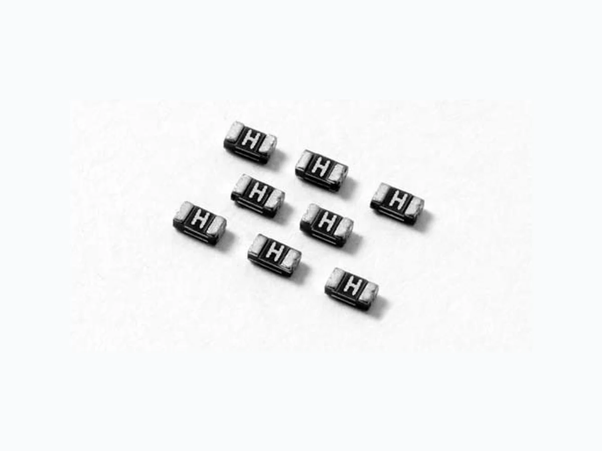
0603L010 LITTELFUSE
Document overview
- Manufacturer or author: Provided By digicamel.com
- PDF pages: 5
Technical content
Features
Applications
t3P)4DPNQMJBOUBOE lead-free t'BTUSFTQPOTFUPGBVMU currents t$PNQBDUEFTJHOTBWFT board space t-PXSFTJTUBODF t-PXQSPmMF t$PNQBUJCMFXJUIIJHI temperature solders t64#QFSJQIFSBMT t%JTLESJWFT t$%30.T t1MVHBOEQMBZQSPUFDUJPO for motherboards and peripherals t1%"TEJHJUBMDBNFSBT t(BNFDPOTPMFQPSU protection AGENCY AGENCY FILE NUMBER E183209 R501 191 18 Agency Approvals
Electrical Characteristics
Part Number Marking I hold (A) I trip (A) V max (Vdc) I max (A) P d max. (W) Maximum Time To Trip Resistance Agency Approvals Current (A) Time (Sec.) R min (Ω) R 1max (Ω) I hold = Hold current: maximum current device will pass without tripping in 20°C still air. I trip = Trip current: minimum current at which the device will trip in 20°C still air. V max = Maximum voltage device can withstand without damage at rated current (I max) I max = Maximum fault current device can withstand without damage at rated voltage (Vmax) P d = Power dissipated from device when in the tripped state at 20°C still air. R min = Minimum resistance of device in initial (un-soldered) state. R 1max = Maximum resistance of device at 20°C measured one hour after tripping or reflow soldering of 260°C for 20 sec. Caution: Operation beyond the specified rating may result in damage and possible arcing and flame.
Revised: October 24, 2008 ©2008 Littelfuse, Inc. POL YFUSE® Resettable PTCs 0603L Series Specifications are subject to change without notice. Please refer to www.littelfuse.com/series/0603L.html for current information. Surface Mount > 0603L Series T emperature Rerating T emperature Rerating Curve -40 -30 -20 -10 0 10 20 30 40 50 60 70 80 10% 30% 50% 70% 90% 110% 130% 150% 170% Temperature (°C) Percentage of Rated Current Average Time Current Curves The average time current curves and Temperature Rerating curve performance is affected by a number or variables, and these curves provided as guidance only. Customer must verify the performance in their application. Ambient Operation Temperature -40°C -20°C 0°C 23°C 40°C 50°C 60°C 70°C 85°C Part Number Hold Current (A) 0603L 0.01 0.1 100 0.1 1 10 100 Current in Amperes Time in Seconds 0.10A 0.20A 0.25A 0.35A
©2008 Littelfuse, Inc. Revised: October 24, 2008 POL YFUSE® Resettable PTCs Specifications are subject to change without notice. Please refer to www.littelfuse.com/series/0603L.html for current information. 0603L Series Surface Mount > 0603L Series 0603L Series Environmental Specifications Operating/Storage T emperature -40°C to +85°C Maximum Device Surface T emperature in T ripped State125°C Passive Aging +85°C, 1000 hours -/+10% typical resistance change Humidity Aging +85°C, 85% R.H.,100 hours -/+15% typical resistance change Thermal Shock MIL–STD–202, Method 107G +85°C/-40°C 20 times -30% typical resistance change Solvent Resistance MIL–STD–202, Method 215 No change Vibration MIL–STD–883C, Method 2007 .1, Condition A No change Moisture Sensitivity Level Level 2, J–STD–020C Physical Specifications T erminal Material Solder-Plated Copper (Solder Material: Matte Tin (Sn)) Lead Solderability Meets EIA Specification RS186-9E, ANSI/J-STD-002, Category 3. Soldering Parameters Profile Feature Pb-Free Assembly Average Ramp-Up Rate (TS(max) to TP) 3°C/second max Pre Heat: Temperature Min (Ts(min)) 150°C Temperature Max (Ts(max)) 200°C Time (Min to Max) (ts) 60 – 180 secs Time Maintained Above: Temperature (TL) 217°C Temperature (tL) 60 – 150 seconds Peak / Classification Temperature (TP) 260 +0/-5 °C Time within 5°C of actual peak Temperature (tp) 20 – 40 seconds Ramp-down Rate 6°C/second max Time 25°C to peak Temperature (TP) 8 minutes Max. -- All temperature refer to topside of the package, measured on the package body surface -- If reflow temperature exceeds the recommended profile, devices may not meet the performance requirements -- Recommended reflow methods: IR, vapor phase oven, hot air oven, N2 environment for lead -- Recommended maximum paste thickness is 0.25mm (0.010 inch) -- Devices can be cleaned using standard industry methods and solvents -- Devices can be reworked using the standard industry practices
Revised: October 24, 2008 ©2008 Littelfuse, Inc. POL YFUSE® Resettable PTCs 0603L Series Specifications are subject to change without notice. Please refer to www.littelfuse.com/series/0603L.html for current information. Surface Mount > 0603L Series Part Ordering Number System PACKAGING STYLE SIZE L: LITTELFUSE SURFACE MOUNT PPTC I HOLD HOLD CURRENT CODE QUANTITY CODE R: Tape & Reel Please refer to table below Y: 4000
0603 L 035 Y R
Inch mm Inch mm Inch mm Inch mm Inch mm Min Max Min Max Min Max Min Max Min Max Min Max Min Max Min Max Min Max Min Max C To p View Pad Layout Side View Bottom View 1mm (.039”) 0.8mm (.032”) D Marking code varies with amperage rating -- See Electrical Characteristics table E A B 1mm (.039”) 1mm (.039”) Solder Pad Layout Part Number Ordering Number I hold (A) I hold Code Packaging Option Quantity Quantity & Packaging Codes 0603L010 0603L010YR 0.10 010 Tape and Reel 4000 YR 0603L020 0603L020YR 0.20 020 Tape and Reel 4000 YR 0603L025 0603L025YR 0.25 025 Tape and Reel 4000 YR 0603L035 0603L035YR 0.35 035 Tape and Reel 4000 YR
©2008 Littelfuse, Inc. Revised: October 24, 2008 POL YFUSE® Resettable PTCs Specifications are subject to change without notice. Please refer to www.littelfuse.com/series/0603L.html for current information. 0603L Series Surface Mount > 0603L Series 0603L Series TAPE SPECIFICATIONS: EIA-481-1 (mm) REEL DIMENSIONS: EIA-481-1 (mm) 0603L010 0603L020 0603L025 0603L035 Leader min. 390 390 T railer min. 160 160 F W CD H K0 B0A0 T F W T ape and Reel Specifications T ape and Reel Diagram