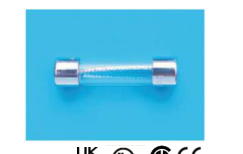
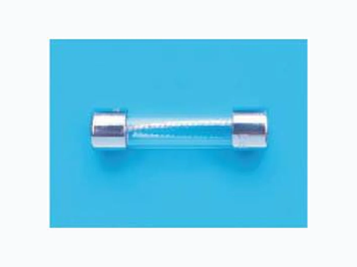
6x32mm Slow Blow, glass tube body cartridge fuse designed, approved and complied with UL and CSA standard 248-14.
Features
Meet UL and CSA standard 248-14 - Wide operating temperature range - Bulk packing available - Full compliance with EU Directive 2011/65/EU and amending directive 2015/863 - Halogen Free - Lead Free
Applications
Provide individual protection for components or internal circuits. - Power supplies - Battery charger - Monitor LEAD FREE =
*I.R.= Interrupting Rating = Short Circuit Rating(Amps)
Testing Current
Blow Time
Minimum
Maximum
100%
4 hrs.
N/A
135%
N/A
1 Hr
200%
5 sec
30 sec
Specifications subject to change without notice
Page 2
2 / 4
Environmental Specifications
Shock Resistance
MIL-STD-202G, Method 213B, Test Condition 1 (100 G's peak for 6 milliseconds; Sawtooth waveform)
Vibration Resistance
MIL-STD-202G, Method 201A (10-55 Hz, 0.06 inch, total excursion).
Salt Spray Resistance
MIL-STD-202G, Method 101E, Test Condition B (48 hrs).
Insulation Resistance
MIL-STD-202G, Method 302, Test Condition A (After Opening) 10,000 ohms minimum.
Solderability
MIL-STD-202G, Method 208H
Resistance to solder Heat
MIL-STD-202G, Method 210F, Test Condition B (260+/-5℃,10+/-1 sec)
Thermal Shock
MIL-STD-202G, Method 107G, Test Condition B (-65℃ to +125℃).
Operating Temperature
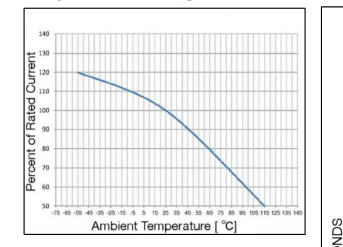
-55℃ to +125℃
Terminal Strength
IEC-68-2-21
Electrical Specifications
Catalog Number
Ampere Rating
Typical Cold Resistance (ohms)
Volt-drop @100%In (Volt) max.
Voltage and Interrupting Ratings
Melting I²T <10 mSec (A² Sec)
Melting I²T @10 In (A² Sec)
Maximum Power Dissipation (W)
Agency Approvals
3SB 500-R
500mA
1.38
1.07
See Table of Safety Approvals on Page 1 for Voltage and associated Interrupting Ratings
4.4
5.4
0.8
Y
Y
3SB 750-R
750mA
0.642
0.68
9
10
0.8
Y
Y
3SB 1-R
1A
0.374
0.59
16
21
0.9
Y
Y
3SB 1.25-R
1.25A
0.248
0.43
25
32
0.9
Y
Y
3SB 1.6-R
1.6A
0.155
0.38
39
50
1.0
Y
Y
3SB 2-R
2A
0.115
0.36
61
79
1.0
Y
Y
3SB 2.5-R
2.5A
0.079
0.29
94
123
1.1
Y
Y
3SB 3-R
3A
0.058
0.27
146
192
1.1
Y
Y
3SB 4-R
4A
0.039
0.23
226
300
1.2
Y
Y
3SB 5-R
5A
0.029
0.22
349
469
1.3
Y
Y
3SB 6-R
6A
0.018
0.19
286
455
1.6
Y
Y
3SB 7-R
7A
0.016
0.18
372
592
1.8
Y
Y
3SB 8-R
8A
0.013
0.17
483
769
1.9
Y
Y
3SB 10-R
10A
0.010
0.17
817
1300
2.3
Y
Y
3SB 12-R
12A
0.008
0.15
1277
2031
2.6
Y
Y
3SB 15-R
15A
0.006
0.15
2123
3377
3.0
Y
Y
Consult manufacturer for other ratings
Specifications subject to change without notice
Page 3
3 / 4
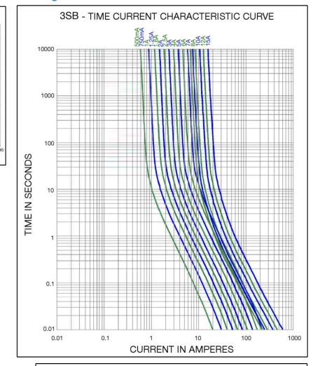
Temperature Derating Curve Average Time Current Curve
Soldering Parameters
Lead-free Wave Soldering Profile
Wave Soldering Parameter
Average ramp-up rate
200℃ / second
Heating rate during preheat
typical 1 - 2℃ / second Max 4℃ / second
Final preheat temperature
within 125℃ of soldering temperature
Peak temperature Tp
260℃
Time within +0℃ / -5℃ of actual peak temperature
10 seconds
Ramp-down rate
5℃ / second max.
Specifications subject to change without notice
Page 4
4 / 4
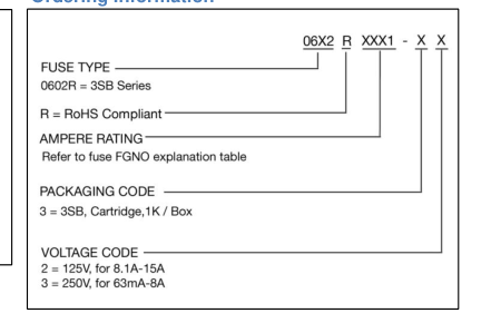
3SB(P) Fuse FGNO Explanation
06X2 R [XXXX] -XX
0602R=3SB; [XXX1]=Ampere Rating; XX=See Ordering Information as below
Catalog number
FGNO / Order Number
3SB 500-R
0602R0501-33
3SB 750-R
0602R0751-33
Catalog number
FGNO / Order Number
3SB 1-R
0602R1001-33
3SB 1.25-R
0602R1251-33
3SB 1.6-R
0602R1601-33
3SB 2-R
0602R2001-33
3SB 2.5-R
0602R2501-33
3SB 3-R
0602R3001-33
3SB 4-R
0602R4001-33
3SB 5-R
0602R5001-33
3SB 6-R
0602R6001-33
3SB 7-R
0602R7001-33
3SB 8-R
0602R8001-33
3SB 10-R
0602R9101-33
3SB 12-R
0602R9121-33
3SB 15-R
0602R9151-33
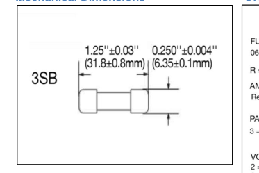
Mechanical Dimensions Ordering Information
Packaging
Packaging Option
Packaging Specification
Quantity
Packaging Code
Inside Tape Spacing
Bulk
N/A
1000
33 / 32
N/A
Specifications subject to change without notice
Selected Specification
Bel Fuse Inc. 0602R3001-33 overview.
Overview
0602R3001-33 is listed in the IC category. Available datasheets include documents from Bel Fuse Inc.. DigiCamel provides a local PDF and searchable HTML technical text for online reference.
Summary
Slow Blow Fuse Series Feb2025
Description
Slow Blow Fuse Series Feb2025
Source title0602R3001-33 Datasheet(PDF) - Bel Fuse Inc.


 Download PDF