
DATASHEET SEARCH SITE
Document overview
- Manufacturer or author: Provided By digicamel.com
- PDF pages: 10
Technical content
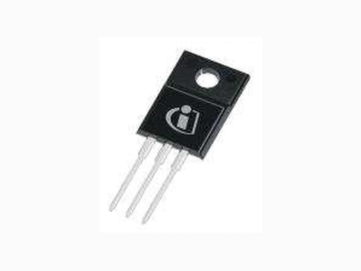
MetalOxideSemiconductorFieldEffectTransistor OptiMOS™Power-Transistor,80V OptiMOS™3Power-Transistor IPA057N08N3G DataSheet Rev.2.2 Final PowerManagement&Multimarket
OptiMOS(TM)3 Power-Transistor
Features
- Ideal for high frequency switching and sync. rec.
- Optimized technology for DC/DC converters
- Excellent gate charge x R DS(on) product (FOM)
- N-channel, normal level
- 100% avalanche tested
- Pb-free plating; RoHS compliant
- Qualified according to JEDEC1) for target applications
- Halogen-free according to IEC61249-2-21
- Fully isolated package (2500 VAC; 1 minute) Maximum ratings, at T j=25 °C, unless otherwise specified Parameter Symbol Conditions Unit Continuous drain current I D T C=25 °C2) 60 A T C=100 °C 43 Pulsed drain current3) I D,pulse T C=25 °C 240 Avalanche energy, single pulse4) E AS I D=60 A, R GS=25 W 290 mJ Gate source voltage V GS ±20 V Power dissipation P tot T C=25 °C 39 W Operating and storage temperature T j, T stg -55 ... 175 °C IEC climatic category; DIN IEC 68-1 55/175/56 to carry 119A. 4) See figure 13 for more detailed information Value 1)J-STD20 and JESD22 3) See figure 3 for more detailed information 2) Current is limited by package; with an RthJC=1 K/W in a standard TO-220 package the chip is able VDS 80 V RDS(on),max 5.7 mW ID 60 A Product Summary Type IPA057N08N3 G Marking 057N08N Rev. 2.2 page 1 2015-08-27
Parameter Symbol Conditions Unit min. typ. max. Thermal characteristics Thermal resistance, junction - case R thJC - - 3.8 K/W Electrical characteristics, at T j=25 °C, unless otherwise specified Static characteristics Drain-source breakdown voltage V (BR)DSS V GS=0 V, I D=1 mA 80 - - V Gate threshold voltage V GS(th) V DS=V GS, I D=90 µA 2 2.8 3.5 Zero gate voltage drain current I DSS V DS=80 V, V GS=0 V, T j=25 °C - 0.1 1 µA V DS=80 V, V GS=0 V, T j=125 °C - 10 100 Gate-source leakage current I GSS V GS=20 V, V DS=0 V - 1 100 nA Drain-source on-state resistance R DS(on) V GS=10 V, I D=60 A - 4.9 5.7 mW V GS=6 V, I D=30 A - 6.3 9.9 Gate resistance R G - 2.2 - W Transconductance g fs |V DS|>2|I D|R DS(on)max, I D=60 A 45 90 - S Values Rev. 2.2 page 2 2015-08-27
Parameter Symbol Conditions Unit min. typ. max. Dynamic characteristics Input capacitance C iss - 3570 4750 pF Output capacitance C oss - 963 1280 Reverse transfer capacitance C rss - 36 - Turn-on delay time t d(on) - 17 - ns Rise time t r - 42 - Turn-off delay time t d(off) - 36 - Fall time t f - 9 - Gate Charge Characteristics5) Gate to source charge Q gs - 18 - nC Gate to drain charge Q gd - 10 - Switching charge Q sw - 18 - Gate charge total Q g - 52 69 Gate plateau voltage V plateau - 5.0 - V Output charge Q oss V DD=40 V, V GS=0 V - 70 93 nC Reverse Diode Diode continous forward current I S - - 60 A Diode pulse current I S,pulse - - 240 Diode forward voltage V SD V GS=0 V, I F=60 A, T j=25 °C - 1.0 1.2 V Reverse recovery time t rr - 64 - ns Reverse recovery charge Q rr - 121 - nC 5) See figure 16 for gate charge parameter definition V R=40 V, I F=I S, di F/dt =100 A/µs T C=25 °C Values V GS=0 V, V DS=40 V, f =1 MHz V DD=40 V, V GS=10 V, I D=60 A, R G,ext=1.6 W V DD=40 V, I D=60 A, V GS=0 to 10 V Rev. 2.2 page 3 2015-08-27
1 Power dissipation 2 Drain current
P tot=f(T C) I D=f(T C); V GS≥10 V 3 Safe operating area 4 Max. transient thermal impedance I D=f(V DS); T C=25 °C; D =0 Z thJC=f(t p) parameter: t p parameter: D =t p/T 1 µs 10 µs 100 µs 1 ms 10 ms DC 100 101 102 103 10-1 100 101 102 ID [A] VDS [V] limited by on-state resistance single pulse 0.01 0.02 0.05 0.1 0.2 0.5 10-5 10-4 10-3 10-2 10-1 100 101 10-2 10-1 100 101 ZthJC [K/W] tp [s] 0 50 100 150 200 Ptot [W] TC [°C] 0 50 100 150 200 ID [A] TC [°C] Rev. 2.2 page 4 2015-08-27
5 Typ. output characteristics 6 Typ. drain-source on resistance I D=f(V DS); T j=25 °C R DS(on)=f(I D); T j=25 °C parameter: V GS parameter: V GS 7 Typ. transfer characteristics 8 Typ. forward transconductance I D=f(V GS); |V DS|>2|I D|R DS(on)max g fs=f(I D); T j=25 °C parameter: T j 4.5 V 5 V 5.5 V 6 V 6.5 V 7 V 8 V 10 V 0 40 80 120 160 200 240 RDS(on) [mW] ID [A] 25 °C 175 °C 120 150 0 2 4 6 8 ID [A] VGS [V] 120 160 0 40 80 120 160 gfs [S] ID [A] 4.5 V 5 V 5.5 V 6 V 6.5 V 7 V 8 V 10 V 120 160 200 240 0 1 2 3 4 5 ID [A] VDS [V] Rev. 2.2 page 5 2015-08-27
9 Drain-source on-state resistance 10 Typ. gate threshold voltage R DS(on)=f(T j); I D=60 A; V GS=10 V V GS(th)=f(T j); V GS=V DS parameter: I D 11 Typ. capacitances 12 Forward characteristics of reverse diode C =f(V DS); V GS=0 V; f =1 MHz I F=f(V SD) parameter: T j typ max -60 -20 20 60 100 140 180 RDS(on) [mW] Tj [°C] 90 µA 900 µA -60 -20 20 60 100 140 180 VGS(th) [V] Tj [°C] Ciss Coss Crss 101 102 103 104 0 20 40 60 80 C [pF] VDS [V] 25 °C 175 °C 25 °C, 98% 175 °C, 98% 100 101 102 103 0 0.5 1 1.5 2 IF [A] VSD [V] Rev. 2.2 page 6 2015-08-27
13 Avalanche characteristics 14 Typ. gate charge I AS=f(t AV); R GS=25 W V GS=f(Q gate); I D=60 A pulsed parameter: T j(start) parameter: V DD
15 Drain-source breakdown voltage 16 Gate charge waveforms
V BR(DSS)=f(T j); I D=1 mA 20 V 40 V 60 V 0 20 40 60 VGS [V] Qgate [nC] -60 -20 20 60 100 140 180 VBR(DSS) [V] Tj [°C] V GS Q gate V gs(th) Q g(th) Q gs Q gd Q sw Q g 25 °C 100 °C 150 °C 100 0.1 1 10 100 1000 IAV [A] tAV [µs] Rev. 2.2 page 7 2015-08-27
Rev. 2.2 page 8 2015-08-27
OptiMOS™3Power-Transistor IPA057N08N3G Rev.2.2,2015-08-27 RevisionHistory IPA057N08N3 G Revision:2015-08-27,Rev.2.2 Previous Revision Revision Date Subjects (major changes since last revision) 2.2 2015-08-27 Update features: "Fully isolated package..." WeListentoYourComments Anyinformationwithinthisdocumentthatyoufeeliswrong,unclearormissingatall?Yourfeedbackwillhelpustocontinuously improvethequalityofthisdocument.Pleasesendyourproposal(includingareferencetothisdocument)to: erratum@infineon.com Publishedby InfineonTechnologiesAG 81726München,Germany ©2015InfineonTechnologiesAG AllRightsReserved. LegalDisclaimer Theinformationgiveninthisdocumentshallinnoeventberegardedasaguaranteeofconditionsorcharacteristics.With respecttoanyexamplesorhintsgivenherein,anytypicalvaluesstatedhereinand/oranyinformationregardingtheapplication ofthedevice,InfineonTechnologiesherebydisclaimsanyandallwarrantiesandliabilitiesofanykind,includingwithout limitation,warrantiesofnon-infringementofintellectualpropertyrightsofanythirdparty. Information Forfurtherinformationontechnology,deliverytermsandconditionsandpricespleasecontactyournearestInfineon TechnologiesOffice(www.infineon.com). Warnings Duetotechnicalrequirements,componentsmaycontaindangeroussubstances.Forinformationonthetypesinquestion, pleasecontactthenearestInfineonTechnologiesOffice. TheInfineonTechnologiescomponentdescribedinthisDataSheetmaybeusedinlife-supportdevicesorsystemsand/or automotive,aviationandaerospaceapplicationsorsystemsonlywiththeexpresswrittenapprovalofInfineonTechnologies,ifa failureofsuchcomponentscanreasonablybeexpectedtocausethefailureofthatlife-support,automotive,aviationand aerospacedeviceorsystemortoaffectthesafetyoreffectivenessofthatdeviceorsystem.Lifesupportdevicesorsystemsare intendedtobeimplantedinthehumanbodyortosupportand/ormaintainandsustainand/orprotecthumanlife.Iftheyfail,itis reasonabletoassumethatthehealthoftheuserorotherpersonsmaybeendangered.