
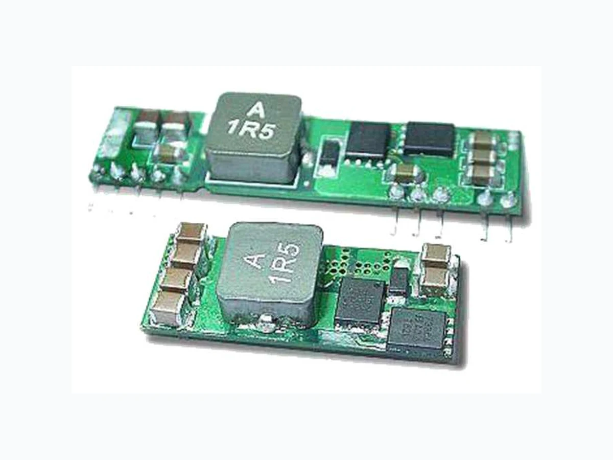
04D-16A YUANDEAN
Document overview
- Manufacturer or author: Provided By www.digicamel.com(FREE DATASHEET DOWNLOAD SITE)
- PDF pages: 3
Technical content
FEATURES : SIP & SMD Packages High Efficiency 92% @ 3.3V Full Load Customized Solutions Available Operating Temperature From -40℃ To +85℃
3 Years Warranty
Input Under-Voltage Lockout Input Range From 8.3VDC To 14.0VDC Output Current Up To 16A Output Voltage Programmable From 0.75VDC To 5.0VDC Via External Resistor DC-DC Converter 04D-16A SERIES Specifications typical at TA=25°C, nominal input voltage and rated output current unless otherwise specified Part Number ON/OFF Logic Input Range Output Voltage Output Current Efficiency (%) 12Vin, 3.3Vdc @16A Min. Load Max. Load 04D-12-16 Negative Vo(set) ≦3.63V Vin = 8.3- 14Vdc 0.75 ~ 5.0Vdc 0A 16A 92% 04D-12-16-SIP YUAN DEAN SCIENTIFIC YUAN DEAN SCIENTIFIC CO.,LTD Rev:0 2018/10/31 04D-16A SERIES Input Specifications Parameters Conditions Min Typ Max Units Voltage Tolerance Vo(set) ≦3.63V 8.3 Vin(nom)=12V 14 Vdc Vo(set) >3.63V 8.3 Vin(nom)=12V 13.2 Vdc Input Current Vin=8.3 to 14.0Vdc; Io(max.) 10 A Input Filter(Note4) C filter No Load Current (Vin=12V,Io=0, Module enabled) Vo(set)=0.75Vdc 40 mA Vo(set)=5.0Vdc 100 mA Under Voltage Lockout Start-up Voltage 7.9 V Shutdown Voltage 7.8 V Input reflected ripple current 5~20MHz, 1uH source impedance:20mAp-p
Applications
Distributed Power Architectures Industry Control System Semiconductor Equipment Microprocessor Power Applications Non-Isolated Single Output
Parameters Conditions Min Typ Max Units Output current 16 A Voltage Tolerance Full load and Vin(nom.) ±2 % Minimum load 0 A Line Regulation Vin=Vin ( min ) to Vin ( max ) at Full Load ±0.3 % Load Regulation No Load to Full Load ±0.4 % Ripple & Noise (Note2) 20MHz bandwidth 75 mVp-p Dynamic load response (Note 2) ΔIo /Δt = 2.5A/uS ,Vin(nom) Peak deviation 200 mV Load change step (25% to 100% or 100% to 25% of Io(max) Setting time (Vo<10%peak deviation) 25 uS Dynamic load Response (Note 3) ΔIo /Δt = 2.5A/uS ,Vin(nom) Peak deviation 100 mV Load change step (25% to 100% or 100% to 25% of Io(max)) Setting time (Vo<10%peak deviation) 25 uS Output current limit 200 % Output short- circuit current Hiccup, automatic recovery External load capacitance ESR ≧1mΩ 1000 uF ESR ≧10mΩ 5000 uF Output voltage overshoot- startup Vin=Vin(min) to Vin(max);F.L 1 % Voltage adjustability (see fig.1) 0.7525 5.0 V General Specifications Parameters Conditions Min Typ Max Units Switching Frequency 300 KHz Isolation voltage None Efficiency See table Dimensions 50.8 X 12.7 X 7.2 mm Weight 6.0 g MTBF (Note 1) MIL-HDBK-217F 6.704 x 10 5 hrs 04D -12 -16 -SIP ,Vo=3.3V Efficiency VS Input Voltage 04D-16A SERIES 04D -12 -16 -SIP ,Vo=3.3V Efficiency VS Output Load YUAN DEAN SCIENTIFIC CO.,LTD Rev:0 2018/10/31 04D -12 -16 -SIP ,Vo=3.3V,Derating Curve
04 D-16A SERIES YUAN DEAN SCIENTIFIC CO.,LTD Environmental Specifications Parameters Conditions Min Typ Max Units Operating temperature range with derating -40 85 ℃ Storage temperature range -55 125 ℃ Thermal shock MIL-STD-810F Over temperature protection 125 ℃ Feature Specifications Parameters Conditions Min Typ Max Units Remote ON/OFF Negative logic(standard) ON = 0V<Vr< 0.3V@I IN 10 uA OFF=2.5V<Vr<Vin(Max)@I IN 1 mA Input current of Remote control pin 0.01 1.0 mA Remote off state input current Nominal Vin 2.0 mA Remote sense range 0.5 V Rise time (Time for Vo to rise from 10% to 90%of Vo(set )) 6 ms Turn-on delay time Case 1 (Note 5) ms Case 2 (Note 6) 3 ms Note : 1. MIL-HDBK-217F Notice2 @Ta=25 ºC, Full load(Ground, Benign, controlled environment). 2. External with Cout = 1μF ceramic//10μF tantalum capacitors. 3. External with Cout = 2×150μF polymer capacitors. 4. It’s necessary to equip the external input capacitors at the input of the module. The capacitors should connect as close as possible to the input terminals that ensuring module stability. The external Cin is 6×47μF ceramic capacitors at least. 5. Case 1 :On/Off input is set to logic low (module on) and then input power is applied (delay from instant at which Vin=Vin(min.) until Vo=10% of Vo(set)) 6. Case 2 :Input power is applied for at least one second and then the On/Off input is set to logic low (delay from instant at which Von/off=0.3V until Vo=10% of Vo(set)) CAUTION : This power module is not internally fused. An input line fuse must always be used. Rev:0 2018/10/31 04D-12-16 04D-12-16-SIP