
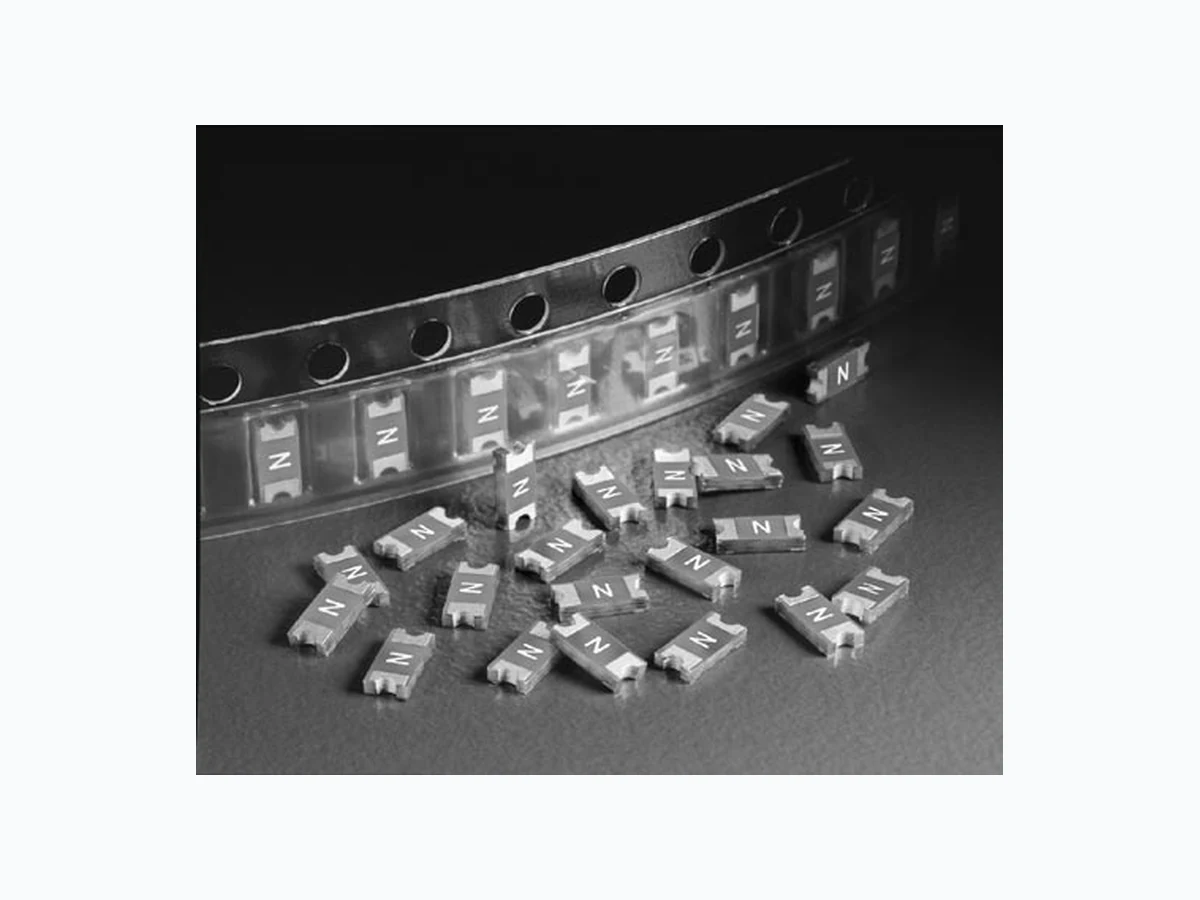
0466002.WR LITTELFUSE
Document overview
- Manufacturer or author: Provided By digicamel.com
- PDF pages: 3
Technical content
Features
Electrical Characteristics for Series
- Product is compatible with lead-free solders and higher temperature profiles
- Product is marked on top surface with code to allow amperage rating identification without testing
- Low profile for height sensitive applications
- Flat top surface for pick- and-place operations
- Element-covering material is resistant to industry standard cleaning operations
- Mounting pad and electrical performance are identical to Littelfuse 429 and 433 Series products
- Alloy-based element construction provides superior inrush withstand characteristics (I 2t) over ceramic or glass-based 1206 chip fuse products % of Ampere rating Opening Time at 25Oc 100% 4 hours, Minimum 200% 5 sec., Maximum 300% 0.2 sec., Maximum Applications Ampere rating (A) Amp code max Voltage rating (V) interrupting rating nominal cold resistance (Ohms) nominal melting i2t (A2sec) nom Voltage Drop (mV) nom power Dissipation (W) Agency Approvals 0.125 .125 125 50A @125 V AC/ DC 4.000 0.00040 552.66 0.0691 x x 0.500 .500 63 50A @63 V AC/DC 0.248 0.0060 158.47 0.0792 x x 2.50 02.5 32 50A @32 V AC/DC 0.024 0.3516 76.99 0.1925 x x Electrical Specifications by Item 1 . Measured at 10% of rated current, 25ºC. 2. Measured at rated voltage.
- Cell phones
- Battery packs
- Digital cameras
- DVD players
- Hard disk drives Secondary protection for space constrained applications: Revised: Jun 16, 2011
Introduction to Circuit ProtectionIntroduction to Circuit Protection Transientology 30 © 2009 Littelfuse, Inc. Specifications are subject to change without notice. Surface Mount Fuses Thin Film > 1206 Size > Very Fast-Acting > 466 Series
466 Series
Please refer to www.littelfuse.com/series/466.html for current information. Average Time Current Curves TIME IN SECONDS CURRENT IN AMPERES 0.01 0.1 0.1 100 10 100 0.001 2 1/2A 1 3/4A 1 1/2A 1 1/4A 3/4A 1/2A 3/8A 1/4A 1/8A reflow condition Pb – free assembly pre Heat - Temperature min (Ts(min)) 150°C - Temperature max (Ts(max)) 200°C - Time (min to max) (ts) 60 – 180 seconds Average ramp-up rate (liquidus Temp (Tl) to peak) 5°C/second max. TS(max) to Tl - ramp-up rate 5°C/second max. reflow - Temperature (Tl) (liquidus) 217°C - Temperature (tl) 60 – 150 seconds peak Temperature (Tp) 250+0/-5 °C Time within 5°c of actual peak Temperature (tp) 20 – 40 seconds ramp-down rate 5°C/second max. Time 25°c to peak Temperature (Tp) 8 minutes max. Do not exceed 260°C Soldering Parameters T emperature Rerating Curve Wave Soldering 260°C, 10 seconds max. Note: 1 . Rerating depicted in this curve is in addition to the standard rerating of 25% for continuous operation. Example: For continuous operation at 70 degrees celsius, the fuse should be rerated as follows: I = (0.75)(0.80)IRAT = (0.60)IRAT 2. The temperature derating curve represents the nominal conditions. For questions about temperature derating curve, please consult Littelfuse technical support for assistance. Time Te mperature TP TL TS(max) TS(min) tP tL tS time to peak temperature (t 25ºC to peak) Ramp-down Ramp-up Preheat Critical Zone TL to TP
31© 2009 Littelfuse, Inc. Specifications are subject to change without notice. Surface Mount Fuses Thin Film > 1206 Size > Very Fast-Acting > 466 Series Please refer to www.littelfuse.com/series/466.html for current information. Dimensions 2.03 (.080") 2.03 (.080") WAVE SOLDER REFLOW SOLDER 3.81 (.150") 1.52 (.060") 0.584 ± 0.076 (0.023" ± 0.003") 0.559 ± 0.127 (0.022" ± 0.005") 0.660 ± 0.127 (0.026" ± 0.005") 1.14 (.045") MARKING CODE VARIES WITH AMPERAGE RATING (SEE CHART) 3.175 ± 0.127 (0.125" ± 0.005") 3.175 ± 0.127 (0.125" ± 0.005") 4.83 (.190") 1.65 (.065") 1.52 (.060") Sn Sn SnCu Coating 1.524 ± 0.127 (0.060" ± 0.005") Packaging Part Numbering System Materials Body: Advanced High Temperature Substrate T erminations: 100% Tin over Nickel over Copper Element Cover Coat: Conformal Coating Operating Temperature – 55 OC to 90OC. Consult temperature rerating curve chart. Thermal Shock Withstands 5 cycles of –55OC to 125OC Humidity MIL-STD-202F, Method 103B, Condition D Product Characteristics Vibration Per MIL-STD-202F, Method 201A Insulation Resistance (After Opening) Greater than 10,000 ohms Resistance to Soldering Heat MIL-STD-202G, Method 210F, Condition D Part Marking System packaging Option packaging Specification Quantity Quantity & packaging code 8mm Tape and Reel EIA-481 Rev. D (IEC 60286, part 3) 5000 NR Amp code marking code .125 B .200 C .250 D .375 E .500 F .750 G 001 . H 1 .25 J 01 .5 K 1 .75 L 002. N 02.5 O 003. P 004. S 005. T 0466002.NRHF SERIES AMP Code ‘HF’ SUFFIX HALOGEN FREE ITEM QUANTITy Code Refer to Amp Code column in the Electrical Specifications table. The dot is poisitioned before the Pack- aging Suffix with whole ratings and within the numbering sequence for fractional ratings. N = 5000 pcs PACKAGING Code R = Tape and Reel Example: .125 amp product is
0466.125 NR HF
(2 amp product shown above).