
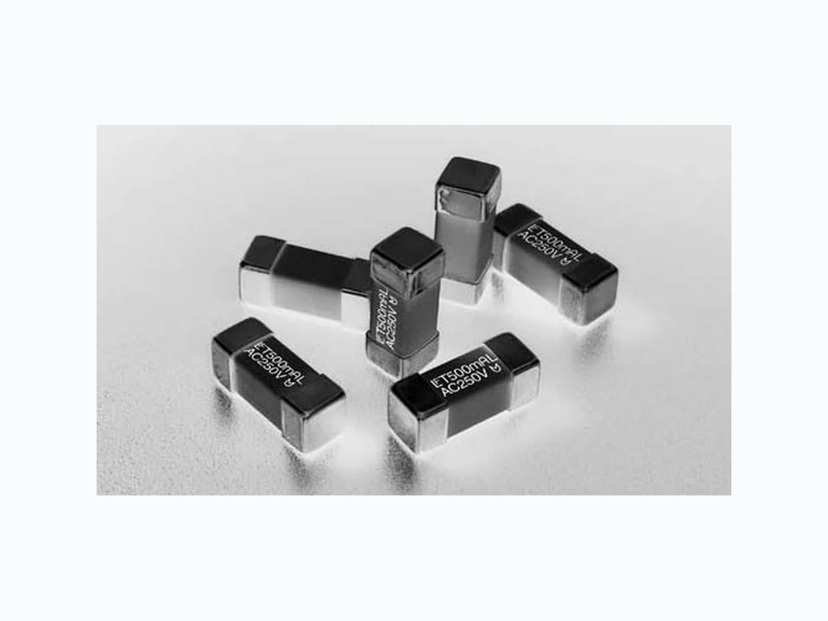
04651.25DR LITTELFUSE
Document overview
- Manufacturer or author: Provided By digicamel.com
- PDF pages: 4
Technical content
Features
t -JTUFEUP*&$ 6OJWFSTBM.PEVMBS 'VTF-JOLT 6.' t 7"$7PMUBHFSBUJOH t 3P)4DPNQMJBOUBOE )BMPHFO'SFF PS E % of Ampere Rating Opening Time IPVS .JOJNVN NJOVUFT .BYJNVN TFD .JO TFD .BY AGENCY AGENCY FILE NUMBER AMPERE RANGE PS E NBK030205-E108480B 1A - 6.3A E184655A,B 250mA - 6.3A 5IF4VSGBDF.PVOU/BOP76.'QSPEVDUGBNJMZ DPNQMJFTXJUI*&$1VCMJDBUJPO*&$6OJWFSTBM .PEVMBS'VTF-JOLT<6.'>5IJT*&$TUBOEBSEIBTCFFO BDDFQUFECZ6-$4"NBLJOHJUUIFåSTUHMPCBMGVTF TUBOEBSE Electrical Specifications by Item Ampere Rating (A) Amp Code Max Voltage Rating (V) Interrupting Rating Nominal Cold Resistance (Ohms) Nominal Melting It (A2sec) Agency Approvals PS E BNQFSFT !7"$ Y Y Y Y Y Y Y Y Y Y Y Y Y Y Y Y Y Y
Applications
t *OEVTUSJBMFRVJQNFOU t .FEJDBMFRVJQNFOU Notes: - l2t calculated at 8ms. - Resistance is measured at 10% of rated current, 25ºC - For information and availability of additional ratings please contact Littelfuse Revised: September 11, 2009
Introduction to Circuit ProtectionIntroduction to Circuit Protection Transientology 82 © 2009 Littelfuse, Inc. Specifications are subject to change without notice. Surface Mount Fuses
465 Series
NANO2® > 250V UMF Time Lag > 465 Series Please refer to www.littelfuse.com/series/465.html for current information. Average Time Current Curves 100 100 0.1 0.01 0.001 1 10 10000.1 1 A 1.25 A 1.6 A 2 A 2.5 A 3.15 A TIME IN SECONDS CURRENT IN AMPERES 4 A 5 A 6.3 A Soldering Parameters T emperature Rerating Curve Reflow Condition 1Co'SFFBTTFNCMZ Pre Heat - Temperature Min (Ts(min)) ¡$ - Temperature Max (Ts(max)) ¡$ - Time (Min to Max) (ts) oTFDT Average ramp up rate (Liquidus Temp (TL) to peak ¡$TFDPOENBY TS(max) to TL - Ramp-up Rate ¡$TFDPOENBY Reflow - Temperature (TL) (Liquidus) ¡$ - Temperature (tL) oTFDPOET Peak Temperature (TP) Time within 5°C of actual peak Temperature (tp) oTFDPOET Ramp-down Rate ¡$TFDPOENBY Time 25°C to peak Temperature (TP) NJOVUFTNBY Do not exceed ¡$ Wave Soldering Parameters ¡$1FBL 5FNQFSBUVSF TFDPOETNBY /PUF %FSBUJOHEFQJDUFEJOUIJTDVSWFJTJOBEEJUJPOUPUIFTUBOEBSEEFSBUJOHPGGPS DPOUJOVPVTPQFSBUJPO Time Temperature TP TL TS(max) TS(min) tP tL tS time to peak temperature (t 25ºC to peak) Ramp-down Ramp-up Preheat Critical Zone TL to TP
83© 2009 Littelfuse, Inc. Specifications are subject to change without notice. Surface Mount Fuses NANO2® > 250V UMF Time Lag > 465 Series Please refer to www.littelfuse.com/series/465.html for current information. Materials #PEZ)JHI1FSGPSNBODF$FSBNJD 5FSNJOBUJPOT4JMWFSQMBUFECSBTT Product Marketing #SBOE "NQFSF3BUJOH 7PMUBHF 3BUJOH 6.'-PHP Operating Temperature oO$UPO$ Moisture Sensitivity Level -FWFM +45%$ Solderability *&$ Insulation Resistance (after opening *&$ .PINNJO! 7%$ Shock .*-45% .FUIPE 5FTU $POEJUJPO" Thermal Shock .*-45% .FUIPE 5FTU$POEJUJPO# DZDMFT oO$ UP¡$ Mechanical Shock .*-45% .FUIPE 5FTU $POEJUJPO" Vibration .*-45% .FUIPE )[ Moisture Resistance .*-45% .FUIPE DZDMFT Salt Spray .*-45% .FUIPE 5FTU $POEJUJPO# IST Resistance to Soldering Heat *&$ Product Characteristics REFLOW SOLDER F 2.8 (.11") 12.1 (.475") 4.5 (.177") 6.7 (.264") 6.8 (.264") WAVE SOLDER 3.5 (.14") AC250V T500mAL 6.9 (.27") 5.6 (.22") 5.6 (.22") 4.5 (.177") Height END CAP TOP VIEW Dimensions Packaging Part Numbering System Packaging Option Packaging Specification Quantity Quantity & Packaging Code QBSU 0465 .500 D R SERIES AMP Code* QUANTITY Code PACKAGING Code 3FGFSUP&MFDUSJDBM $IBSBDUFSJTUJDTUBCMF QDT 5BQFBOE3FFM *Example: BNQQSPEVDUJT02.5%3 BNQQSPEVDUTIPXOBCPWF
Introduction to Circuit ProtectionIntroduction to Circuit Protection Transientology 84 © 2009 Littelfuse, Inc. Specifications are subject to change without notice.