
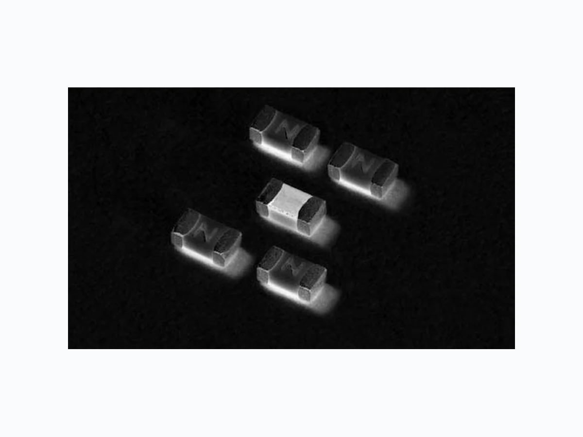
0441005WR LITTELFUSE
Document overview
- Manufacturer or author: Provided By digicamel.com
- PDF pages: 4
Technical content
Features
Electrical Characteristics
from -55ºC to 150ºC t -FBEGSFFBOE RoHS compliant t 4VJUBCMFGPSCPUIMFBEFE and lead-free reflow / wave soldering t 6MUSBIJHI*¤UWBMVFT % of Ampere Rating Ampere Rating Opening Time at 25ºC 100% 2A - 6A 4 Hours Minimum 350% 2A - 6A 5 Seconds Maximum
Applications
Electrical Specifications by Item Notes: 1 . DC Interrupting Rating tested at rated voltage with time constant < 0.8 msecs. 2. Nominal Resistance measured with < 10% rated current. 3. Nominal Melting I²t measured at 1 msec. opening time. 4. Nominal Voltage Drop measured at rated current after temperature has stabilized. t )BOEIFME&MFDUSPOJDT t -$%%JTQMBZT t #BUUFSZ1BDLT t )BSE%JTL%SJWFT t 4%.FNPSZ$BSET t "VUPNPUJWF&MFDUSPOJDT Devices designed to carry out rated current for 4 hours minimum. It is recommended that devices be operated continuously at no more than 80% rated current. See “Temperature Rerating Curve”for additional rerating information. Devices designed to be mounted with marking code facing up. Ampere Rating (A) Amp Code Max. Voltage Rating (V) Interrupting Rating Nominal Resistance (Ohms)2 Nominal Melting I2t (A2Sec.)3 Nominal Voltage Drop At Rated Current (V)4 Nominal Power Dissipation At Rated Current (W) Agency Approvals 2 002. 32
50 A @ 32 VDC
0.0302 0.3103 0.0551 0.110 X X Revised: June 15, 2010
Introduction to Circuit ProtectionIntroduction to Circuit Protection Transientology 2 © 2009 Littelfuse, Inc. Specifications are subject to change without notice. Surface Mount Fuses
441 Series
Ceramic Fuse > 441 Series Please refer to www.littelfuse.com/series/441.html for current information. Average Time Current Curves 0.001 0.01 0.1 100 1 10 100 2.5A 3.5A TIME IN SECONDS CURRENT IN AMPERES Reflow Condition 1CoGSFFBTTFNCMZ Pre Heat - Temperature Min (Ts(min)) 150°C - Temperature Max (Ts(max)) 200°C - Time (Min to Max) (ts) oTFDPOET Average Ramp-up Rate (Liquidus Temp (TL) to peak) 3°C/second max. TS(max) to TL - Ramp-up Rate 5°C/second max. Reflow - Temperature (TL) (Liquidus) 217°C - Temperature (tL) oTFDPOET Peak Temperature (TP) 260+0/-5 °C Time within 5°C of actual peak Temperature (tp) oTFDPOET Ramp-down Rate 6°C/second max. Time 25°C to peak Temperature (TP) 8 minutes max. Do not exceed 260°C Soldering Parameters T emperature Rerating Curve 100 120 140 -65 -45 -25 -5 15 35 55 75 95 115 135 155 TEMPERATURE (°C) PERCENT OF RATING For continuous operation at 75 degrees celsius, the fuse should be rerated as follows: I = (0.80)(0.85)I RAT = (0.68)IRAT Note: 1 . Rerating depicted in this curve is in addition to the standard rerating of 20% for continuous operation. Wave Soldering 260°C, 10 seconds max. Time Temperature TP TL TS(max) TS(min) tP tL tS time to peak temperature (t 25ºC to peak) Ramp-down Ramp-up Preheat Critical Zone TL to TP
3© 2009 Littelfuse, Inc. Specifications are subject to change without notice. Surface Mount Fuses Ceramic Fuse > 441 Series Please refer to www.littelfuse.com/series/441.html for current information. Body: Advanced Ceramic T erminations: Ag / Ni / Sn (100% Lead-free) Element Cover Coating: Lead-free Glass Moisture Sensitivity Level *1$+&%&$+45%$ -FWFM $POEJUJPO$ Humidity .*-45% .FUIPE# $POEJUJPOT% ESD Immunity *&$ L7%JSFDU Resistance to Solder Heat .*-45% .FUIPE' $POEJUJPO# Product Characteristics Moisture Resistance MIL -STD-202, Method 106G Thermal Shock MIL -STD-202, Method 107G, $POEJUJPO# Mechanical Shock .*-45% .FUIPE# Condition A Vibration MIL -STD-202, Method 201A Vibration, High Frequency MIL -STD-202, Method 204D, Condition D Dissolution of Metallization Condition D T erminal Strength *&$ Dimensions 1.54 +/- 0.150 [0.061 +/- 0.006] 0.74 [0.029] 1.00 [0.039] 1.94 [0.076] 0.60 [0.024] 0.502 +/- 0.080 [0.020 +/- 0.003] 0.530 +/- 0.150 [0.021 +/- 0.006] 0.850 +/- 0.150 [0.033 +/- 0.006] 0.432 +/- 0.150 [0.017 +/- 0.006] Packaging Part Marking System Packaging Option Packaging Specification Quantity Quantity & Packaging Code QBSU 3000 WR Part Numbering System 0441 005. W R SERIES AMP CODE QUANTITY CODE PACKING CODE W = 3000 pcs 3FFM1BDL Amp Code Marking Code 002. N 02.5 O 003. P 03.5 R 004. S 005. T 006. U
Introduction to Circuit ProtectionIntroduction to Circuit Protection Transientology 4 © 2009 Littelfuse, Inc. Specifications are subject to change without notice.