


 Download PDF
DATASHEET SEARCH SITE
Document overview
- PDF pages: 8
Technical content
Page 1
NTC Diode
Thermometrics Thermistors
A range of NTC chip thermistors in DO-35 style glass package (diode outline) with axial soldercoated copper-clad steel wires.
- Designed for accurate temperature measurement, control and compensation
- Tight tolerances on resistance and B value
- Operation up to 482°F (250°C) with excellent stability
- Glass body provides hermetic seal and voltage insulation and excellent stability
- Designed for cost effective solid state sensor
- Lead-wires metallurgically bonded to thermistor element for improved reliability (Type GE only)
- Resistant to corrosive atmospheres and harsh environments
Amphenol
Advanced Sensors
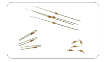
- Available on axial bandolier to IEC-286-1/ EIA-468A and packet taped to EIA RS-481 for MELF.
- Also available loose-packed with axial, radial and SMD wire forms
- Suitable for automotive, telecom (battery packs), HVAC and white goods applications
- Temperature sensing for household appliances such as rice cookers, electronic ranges, ovens, etc.
- Temperature sensing for industrial products such as pharmaceuticals, chemicals, food, etc.components.
Page 2
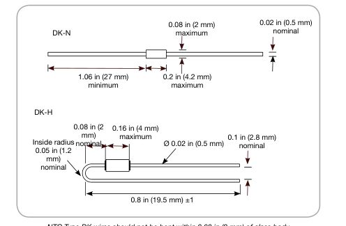
Type DK Specifications
Chip thermistor in DO-35 glass package
Options
- Other resistance values within the ranges
shown; e.g. code DKA302\*2 for 3000 Ω ±2% at 77°F (25°C)
- Reference temperatures in the range 0°F
to 302°F (-18°C to 150°C)
- Operation to 572°F (300°C) (no solder
coating on wires)
- Wire lengths 0.16 in to 1.26 in (4 mm to
NTC Type DK wires should not be bent within 0.08 in (2 mm) of glass body
32 mm)
±0.04 in (±1 mm) for DK-N; up to 1.02 in (26 mm) for DK-H
Data
- Operating temperature: -40°F to 482°F (-40°C to 250°C)
Coding
- Thermal time constant: 7 seconds (cooling in air)
Replace \* in the codes shown below as follows:
- Dissipation factor: 3.0 mW/K
- Axial, loose-packed: N
- Mass: 0.2 g
- Axial, bandoliered: B
- Packing/MOQ: 1000/box (loose),
5000/reel (bandoliered)
- Radial, loose-packed: H
- Surface mount, loose-packed: M
R25 W Material B 25/85 K Code
Code Code Code
system
R25 ±2% R25 ±3% R25 ±5%
R25 ±10%
2000 2 3540 ±1% DKA202\*2
DKA202\*3 DKA202\*5
DKA202\*10
5000 2 3540 ±1% DKA502\*2
DKA502\*3 DKA502\*5
DKA502\*10
10,000 2 3540 ±1% DKA103\*2
DKA103\*3 DKA103\*5
DKA103\*10
10,000 5A 3730 ±2%
DKC103\*3 DKC103\*5
DKC103\*10
12,000 5A 3730 ±2% DKC123\*2 DKC123\*3 DKC123\*5
DKC123\*10
10,000 3 3960 ±1% DKF103\*2
DKF103\*3 DKF103\*5
DKF103\*10
20,000 3 3960 ±1% DKF203\*2
DKF203\*3 DKF203\*5
DKF203\*10
30,000 3 3960 ±1% DKF303\*2
DKF303\*3 DKF303\*5
DKF303\*10
50,000 3 3960 ±1% DKF503\*2
DKF503\*3 DKF503\*5
DKF503\*10
100,000 3 3960 ±1% DKF104\*2
DKF104\*3 DKF104\*5
DKF104\*10
200,000 G 4263 ±2%
DKG204\*5 DKG204\*10
500,000 D 4573 ±2%
DKD504\*5 DKD504\*10
1,000,000 D
4573 ±2%
DKD105\*5 DKD105\*10
See separate tables for resistance-temperature data.. Consult factory for additional tolerance requirements.
Page 3
Type DKM Specifications
Glass encapsulated SMD thermistor
Description
A range of thermistors in DO-35 style glass package (diode outline formed for surface lead-wires and applications) with solder- coated copper-clad steel lead-wires.
Options
- Other resistance values within the ranges
shown; e.g. code DKA302M2 for 3000 Ω ±2% at 77°F (25°C)
- Reference temperatures in the range 32°F to
302°F (0°C to 150°C)
- For tape and reel, add suffix “AB”
- Operation to 572°F (300°C); no solder
coating on lead-wires
R25 W Material B 25/85 K
Code Code
System
R25 ±2% R25 ±3%
2000 2 3540 ±1%
DKA202M2 DKA202M3
5000 2 3540 ±1%
DKA502M\*2 DKA502M3
10,000 2 3540 ±1%
DKA103M2 DKA103M3
10,000 5A 3730 ±2%
DKC103M3
10,000 3 3960 ±1%
DKF103M2 DKF103M3
20,000 3 3960 ±1%
DKF203M2 DKF203M3
30,000 3 3960 ±1%
DKF303M2 DKF303M3
50,000 3 3960 ±1%
DKF503M2 DKF503M3
100,000 3 3960 ±1%
DKF104M2 DKF104M3
200,000 G 4263 ±2%
500,000 D 4573 ±2%
1,000,000 D
4573 ±2%
See separate tables for resistance-temperature data.. Consult factory for additional tolerance requirements.
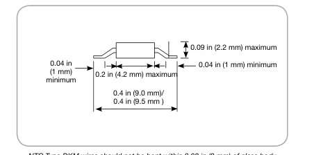
NTC Type DKM wires should not be bent within 0.08 in (2 mm) of glass body
Data
- Operating temperature: -40°F to 482°F (-40°C to 250°C)
- Thermal time constant: 7 seconds (cooling in air)
- Dissipation factor: 3.0 mW/K
- Mass: 0.2 g
- Packing/MOQ: 1000/box (loose)
Code Code R25 ±5% R25 ±10%
DKA202M\*5 DKA202M10
DKA502M5 DKA502M10
DKA103M5 DKA103M10
DKC103M5 DKC103M10
DKF103M5 DKF103M10
DKF203M5 DKF203M10
DKF303M5 DKF303M10
DKF503M5 DKF503M10
DKF104M5 DKF104M10
DKG204M5 DKG204M10
DKD504M5 DKD504M10
DKD105M5 DKD105M10
Page 4
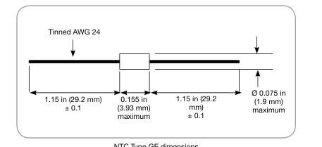
Type GE Specifications
Glass encapsulated DO-35 package
Options
- For reel taping “R” suffix
- Nickel leads for welding
NTC Type GE dimensions
- Other resistances in the range 250 Ω
to 5 MΩ
Data
- Other tolerances, tolerances at other
- Standard resistance tolerance: ±10% @ 77°F (25°C)
temperatures
- Dissipation constant: 3.0 mW/K
- Alternative leads lengths, lead
- Time constant: 7 seconds
materials
- Operating range: -58°F to 400°F (-50°C to 204°C
- Can be expanded to 572°F (300°C)
with nickel leads
Ro@25° Material System Beta 25/85
Type Number
C (W )
250 GE5.5\*
2983 AL03006-165.9-55-K
500 GE5.5\*
2983 AL03006-331.8-55-K
1K GE7.3
3499 AL03006-624-73-K
2K GE7.3
3499 AL03006-1248-73-K
2786 GE10.1
4102 AL03006-1576-101-K
3K GE7.6
3553 AL03006-1847-76-K
4K GE7.6
3553 AL03006-2463-76-K
5K GE7.6
3553 AL03006-3079-76-K
10K GE9.7A
3992 AL03006-5818-97-K
20K GE9.8
3974 AL03006-11.7K-98-K
30K GE9.8
3974 AL03006-17.53K-98-K
50K GE9.7B
3952 AL03006-29.1K-97-K
100K GE9.7B
3952 AL03006-58.2K-97-K
200K GE12.3
4365 AL03006-111.3K- 123-K
500K GE13.8
4567 AL03006-269.8K- 138-K
1M GE14.5
4661 AL03006-535K-145-K
5M GE16.4
4848 AL03006-2.6M-164-K
\*maximum operating temperature 302°F (150°C)
Page 5
Type MELF Specifications
Glass encapsulated SMD thermistor
Description
Hermetically sealed, glass encapsulated thermistor in SOD-80 SMD package.
Options
- For ±5% @ 77°F (25°C), replace “K” with “J”
- For ±3% @ 77°F (25°C), replace “K” with “H”
- For ±2% @ 77°F (25°C), replace “K” with “G”
- For reel taping add “R” suffix
- Other resistances in the range 250 Ω to 5
MΩ available
- Other tolerances, tolerances at other
temperatures
Ro@25° Material System Beta 25/85
Type Number
C (W )
250 GE5.5\*
2983 03006-165.9-55-K
500 GE5.5\*
2983 03006-331.8-55-K
1K GE7.3
3499 03006-624-73-K
2K GE7.3
3499 03006-1248-73-K
2786 GE10.1
4102 03006-1576-101-K
3K GE7.6
3553 03006-1847-76-K
4K GE7.6
3553 03006-2463-76-K
5K GE7.6
3553 03006-3079-76-K
10K GE9.7A
3992 03006-5818-97-K
20K GE9.8
3974 03006-11.7K-98-K
30K GE9.8
3974 03006-17.53K-98-K
50K GE9.7B
3952 03006-29.1K-97-K
100K GE9.7B
3952 03006-58.2-97-K
200K GE12.3
4365 03006-111.3K-123-K
500K GE13.8
4567 03006-269.8K-138-K
1M GE14.5
4661 03006-535K-145-K
5M GE16.4
4848 03006-2.6M-164-K
\*maximum operating temperature 302°F (150°C)
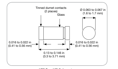
NTC Type MELF dimensions
Data
- Standard resistance tolerance: ±10% @ 77°F (25°C)
- Dissipation constant: 3.0 mW/°C
- Time constant: 7 seconds
- Operating range: -58°F to 400°F (-50°C to 204°C
Page 6
Type TH Specifications
Glass encapsulated radial lead thermistor
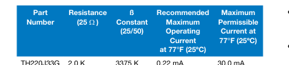
TH225J13G 2.545 K
3745 K 0.22 mA
30.0 mA
TH238J34G 3.896 K
3434 K 0.20 mA
26.5 mA
TH253J34G 5.369 K
3434 K 0.16 mA
24.0 mA
TH310J34G 10.74 K
3434 K 0.13 mA
20.0 mA
TH310J36G 10.0 K
3684 K 0.14 mA
20.0 mA
TH310J39G 10.0 K
3933 K 0.14 mA
20.0 mA
TH315J39G 15.0 K
3933 K 0.12 mA
17.0 mA
TH320J39G 20.0 K
3952 K 0.10 mA
15.0 mA
TH349J39G 49.12 K
3952 K 0.06 mA
10.0 mA
TH350J39G 50.0 K
3952 K 0.06 mA
10.0 mA
TH398J40G 98.63 K
4014 K 0.045 mA
5.0 mA
TH410J40G 100.0 K
4014 K 0.045 mA
5.0 mA
TH420J34G 200.0 K
3450 K 0.015 mA
3.5 mA
TH423J41G 231.4 K
4176 K 0.015 mA
3.5 mA
TH510J44G 1,000 K
4491 K 0.007 mA
1.5 mA
TH513J44G 1,388 K
4491 K 0.005 mA
1.0 mA
- The tolerance of resistance is ±5% for standard
device
- The tolerance of B constant is ±2% for
standard device The constant is determined by the equation: B = 3853.9 In (R25/R50) R25 and R50 represent the thermistor resistance at 77°F and 122°F (25°C and 50°C) respectively
- Others: For non-standard devices, consult
Thermometrics
Dissipation Time
Operating
Rated Power
Factor
Constant
Temperature
at 77°F (25ºC)
(in still air)
(in still air)
Range
2.0 (mW/ºC)
25 (seconds) -40°F to 482°F
25 mW
(-40°C to 250ºC)
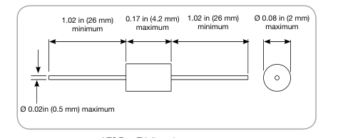
NTC Type TH dimensions
Page 7
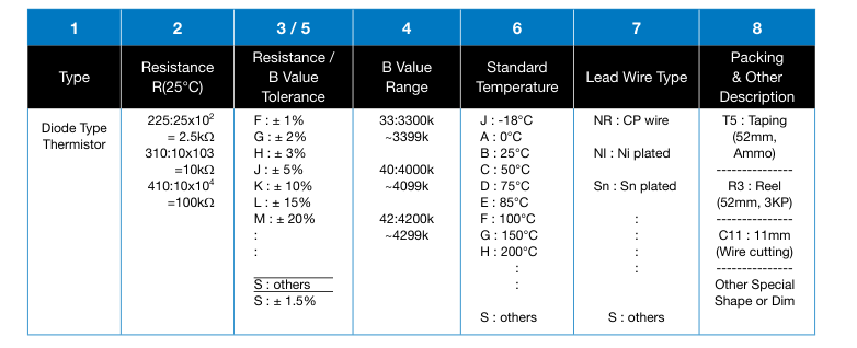
Explanation of Part Number
-
TH
410
S 40 F
D
SN
T5
(1)
(2)
(3) (4) (5)
(6)
(7)
(8)
Page 8
Amphenol
www.amphenol-sensors.com
© 2015 Amphenol Corporation. All Rights Reserved. Specifications are subject to change without notice.
Advanced Sensors
Other company names and product names used in this document are the registered trademarks or
trademarks of their respective owners.