
 Download PDF
DATASHEET SEARCH SITE
Document overview
- PDF pages: 4
Technical content
Page 1
Low Inductance Capacitors
Introduction
The signal integrity characteristics of a Power Delivery Network (PDN) are becoming critical aspects of board level and semiconductor package designs due to higher operating frequencies, larger power demands, and the ever shrinking lower and upper voltage limits around low operating voltages. These power system challenges are coming from mainstream designs with operating frequencies of 300MHz or greater, modest ICs with power demand of 15 watts or more, and operating voltages below 3 volts. The classic PDN topology is comprised of a series of capacitor stages. Figure 1 is an example of this architecture with multiple capacitor stages. An ideal capacitor can transfer all its stored energy to a load
instantly. A real capacitor has parasitics that prevent instantaneous transfer of a capacitor’s stored energy. The true nature of a capacitor can be modeled as an RLC equivalent circuit. For most simulation purposes, it is possible to model the characteristics of a real capacitor with one
capacitor, one resistor, and one inductor. The RLC values in this model are commonly referred to as equivalent series capacitance (ESC), equivalent series resistance (ESR), and equivalent series inductance (ESL). The ESL of a capacitor determines the speed of energy transfer to a load. The lower the ESL of a capacitor, the faster that energy can be transferred to a load. Historically, there has been a tradeoff between energy storage (capacitance) and inductance (speed of energy delivery). Low ESL devices typically have low capacitance. Likewise, higher capacitance devices typically have higher ESLs. This tradeoff between ESL (speed of energy delivery) and capacitance (energy
storage) drives the PDN design topology that places the fastest low ESL capacitors as close to the load as possible. Low Inductance MLCCs are found on semiconductor packages and on boards as close as possible to the load.
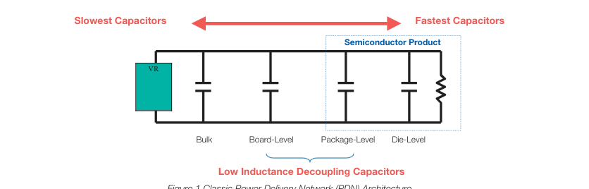
Figure 1 Classic Power Delivery Network (PDN) Architecture
LOW INDUCTANCE CHIP CAPACITORS
The key physical characteristic determining equivalent series inductance (ESL) of a capacitor is the size of the current loop it creates. The smaller the current loop, the lower the ESL. A standard surface mount MLCC is rectangular in shape with electrical terminations on its shorter sides. A Low Inductance Chip Capacitor (LICC) sometimes referred to as Reverse Geometry Capacitor (RGC) has its terminations on the longer side of its rectangular shape. When the distance between terminations is reduced, the size of the current loop is reduced. Since the size of the current loop is the primary driver of inductance, an 0306 with a smaller current loop has significantly lower ESL then an 0603.
The reduction in ESL varies by EIA size, however, ESL is typically reduced 60% or more with an LICC versus a standard MLCC.
INTERDIGITATED CAPACITORS
The size of a current loop has the greatest impact on the ESL characteristics of a surface mount capacitor. There is a secondary method for decreasing the ESL of a capacitor. This secondary method uses adjacent opposing current loops to reduce ESL. The InterDigitated Capacitor (IDC) utilizes both primary and secondary methods of reducing inductance. The IDC architecture shrinks the distance between terminations to minimize the current loop size, then further reduces inductance by creating adjacent opposing current loops. An IDC is one single capacitor with an internal structure that has been optimized for low ESL. Similar to standard MLCC versus LICCs, the reduction in ESL varies by EIA case size.
Typically, for the same EIA size, an IDC delivers an ESL that is at least 80% lower than an MLCC.
Page 2
Low Inductance Capacitors
Introduction
LAND GRID ARRAY (LGA) CAPACITORS
Land Grid Array (LGA) capacitors are based on the first Low ESL MLCC technology created to specifically address the design needs of current day Power Delivery Networks (PDNs). This is the 3rd low inductance capacitor technology developed by AVX. LGA technology provides engineers with new options. The LGA internal structure and manufacturing technology eliminates the historic need for a device to be physically small to create small current loops to minimize inductance. The first family of LGA products are 2 terminal devices. A 2 terminal 0306 LGA delivers ESL performance that is equal to or better than an 0306 8 terminal IDC. The 2 terminal 0805 LGA delivers ESL performance that approaches the 0508
8 terminal IDC. New designs that would have used 8 terminal IDCs are moving to 2 terminal LGAs because the layout is easier for a 2 terminal device and manufacturing yield is better for a 2 terminal LGA versus an 8 terminal IDC. LGA technology is also used in a 4 terminal family of products that AVX is sampling and will formerly introduce in 2008. Beyond 2008, there are new multi-terminal LGA product families that will provide even more attractive options for PDN designers.
LOW INDUCTANCE CHIP ARRAYS (LICA®)
The LICA® product family is the result of a joint development effort between AVX and IBM to develop a high performance MLCC family of decoupling capacitors. LICA was introduced in the 1980s and remains the leading choice of designers in high performance semiconductor packages and high reliability board level decoupling applications. LICA® products are used in 99.999% uptime semiconductor package applications on both ceramic and organic substrates. The C4 solder ball termination option is the perfect compliment to flip-chip packaging technology. Mainframe class CPUs, ultimate performance multi-chip modules, and communications systems that must have the reliability of 5 9’s use LICA®.
LICA® products with either Sn/Pb or Pb-free solder balls are used for decoupling in high reliability military and aerospace applications. These LICA® devices are used for decoupling of large pin count FPGAs, ASICs, CPUs, and other high power ICs with low operating voltages. When high reliability decoupling applications require the very lowest ESL capacitors, LICA® products are the best option.
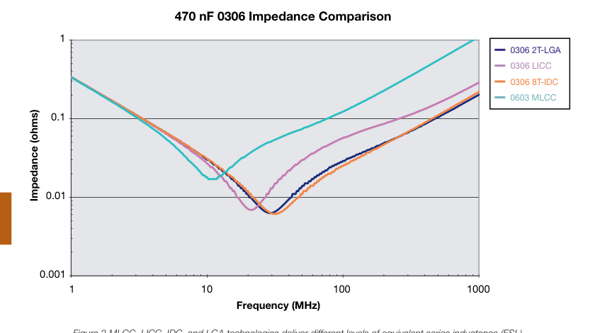
Figure 2 MLCC, LICC, IDC, and LGA technologies deliver different levels of equivalent series inductance (ESL).
Page 3
Low Inductance Capacitors (RoHS)
0612/0508/0306/0204 LICC (Low Inductance Chip Capacitors)
GENERAL DESCRIPTION
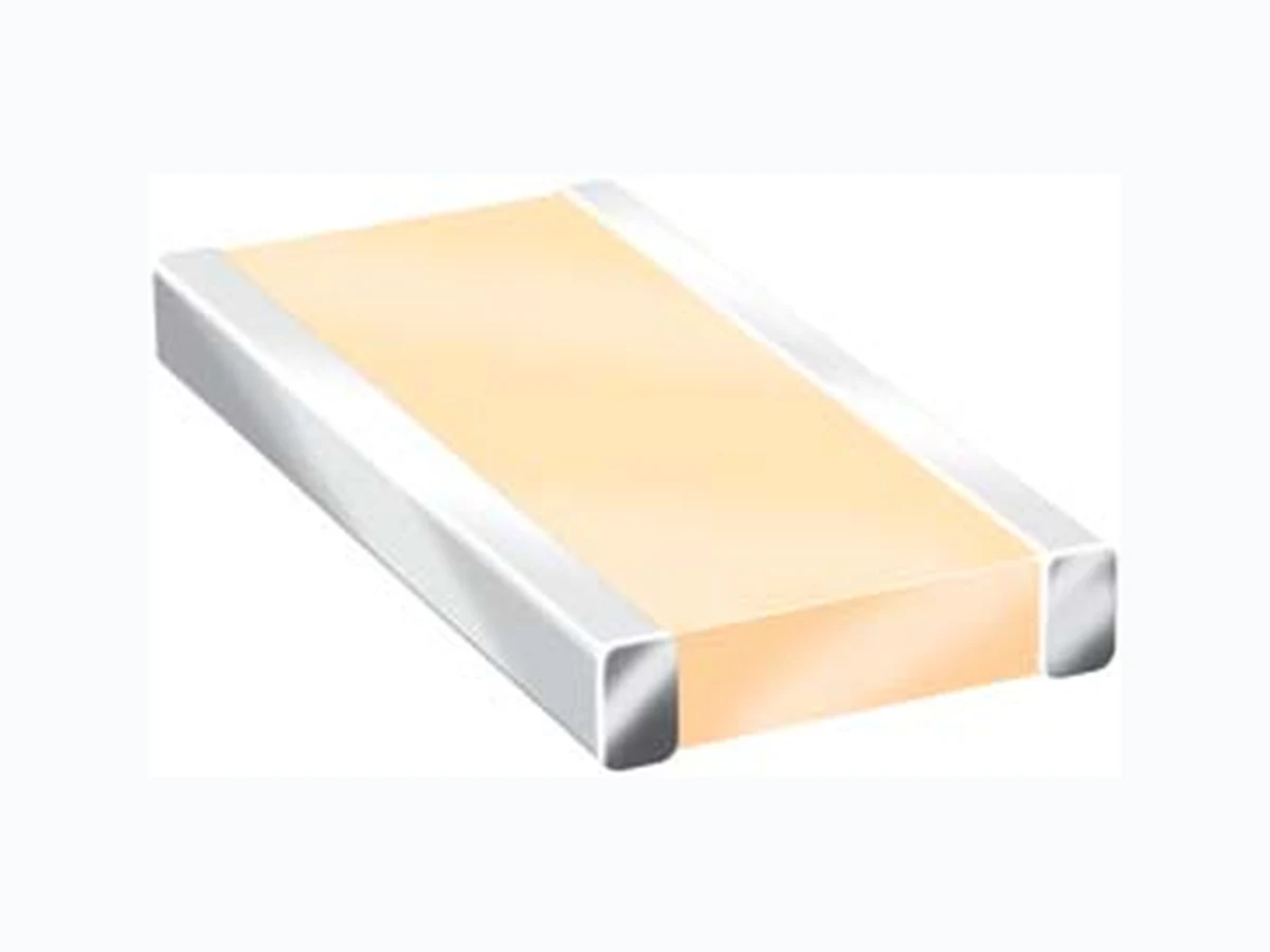
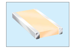
The key physical characteristic determining equivalent series inductance (ESL) of a capacitor is the size of the current loop it creates. The smaller the current loop, the lower the ESL. A standard surface mount MLCC is rectangular in shape with electrical terminations on its shorter sides. A Low Inductance Chip Capacitor (LICC) sometimes referred to as Reverse Geometry Capacitor (RGC) has its terminations on the longer sides of its rectangular shape. The image on the right shows the termination differences between an MLCC and an LICC.
LICC
MLCC
When the distance between terminations is reduced, the size of the current loop is reduced. Since the size of the current loop is the primary driver of inductance, an 0306
PERFORMANCE CHARACTERISTICS
with a smaller current loop has significantly lower ESL then an 0603. The reduction in ESL varies by EIA size,
| Capacitance Tolerances | K = ±10%; M = ±20% |
| Operation Temperature Range | X7R = -55°C to +125°C X5R = -55°C to +85°C X7S = -55°C to +125°C |
| Temperature Coefficient | X7R, X5R = ±15%; X7S = ±22% |
| Voltage Ratings | 4, 6.3, 10, 16, 25 VDC |
| Dissipation Factor | 4V, 6.3V = 6.5% max; 10V = 5.0% max; 16V = 3.5% max; 25V = 3.0% max |
| Insulation Resistance (@+25°C, RVDC) | 100,000MΩ min, or 1,000MΩ per μF min.,whichever is less |
however, ESL is typically reduced 60% or more with an LICC versus a standard MLCC. AVX LICC products are available with a lead-free finish of plated Nickel/Tin.
HOW TO ORDER
0612
Z
D
105
M
A
T
2
A\*
Size Voltage Dielectric
Capacitance
Capacitance Failure Rate Terminations
Packaging
Thickness
Code (In pF)
Tolerance
0204
4 = 4V
C = X7R
A = N/A T = Plated Ni
Available
Thickness
2 Sig. Digits +
K = ±10%
0306 6 = 6.3V
D = X5R
and Sn 2 = 7" Reel
mm (in)
Number of Zeros
M = ±20%
0508 Z = 10V
W = X6S
4 = 13" Reel 0.35 (0.014)
0612 Y = 16V
Z = X7S
0.56 (0.022)
3 = 25V
0.61 (0.024)
5 = 50V
0.76 (0.030) 1.02 (0.040)
NOTE: Contact factory for availability of Termination and Tolerance Options for Specific Part Numbers.
1.27 (0.050)
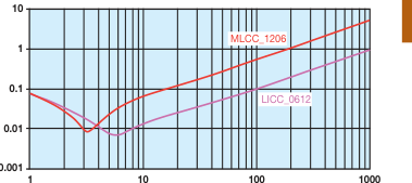
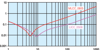
TYPICAL IMPEDANCE CHARACTERISTICS
Frequency (MHz)
Frequency (MHz)
Page 4
Low Inductance Capacitors (RoHS)
0612/0508/0306/0204 LICC (Low Inductance Chip Capacitors)