
BUS BURKERT
Document overview
- Manufacturer or author: Provided By digicamel.com
- PDF pages: 42
Technical content
Datasheet sections
- 1 Symbols used
- 2 Introduction
- 2.1 Preface
- 2.5 Bürkert quality standard
- 3 Creating a rough project plan
- 3.1 Block diagram, devices, postion, protocols
- 4 Getting to know the basics of a büS infrastructure – accessories, cables, pin assignment
- 4.1 What is the purpose of the various accessories
- 4.2 Accessories
- 4.2.1 Y-connector
- 4.2.2 Passive junction box
- 4.2.3 Gender changer
- 4.2.4 Termination
- 4.3 Cable configuration
- 4.3.1 Characteristic impedance and cables standards
- 4.3.2 Connecting cables
- 4.3.3 Extension cables
- 4.4 Pin assignment
- 4.4.1 M12 connector male, 5-pin (A-coded)
- 4.4.2 M12 connector male, 8-pin (A-coded)
- 4.4.3 Terminal block, 5-pin
- 4.4.4 Terminal block, 4-pin
- 5 Getting to know the büS topologies
- 5.2 Common terms of bus topology
- 5.2.1 Trunk line
- 5.2.2 Stub line
- 5.2.3 Overview of cable lengths
- 5.2.4 Example
- 5.3.1 Line topology (daisy chain)
- 5.3.2 Line topology with stub lines
- 5.3.3 Star topology
- 5.4.1 Tree topology
- 5.5 Which topologies are NOT permitted
- 5.5.1 Ring topology
- 6 Detailed project plan
- 6.1 Floor plan
- 6.1.1 Network with a junction box
Datasheet sections
- 6.1.2 Network with Y-connectors
- 6.1.3 Mixed network
- 7 Technical know-how
- 7.1 Termination resistors
- 7.2 Connection for diagnostics
- 8 Detailed project plan
- 8.1 Completion – floor plan
- 8.1.1 Network with a junction box
- 8.1.2 Network with Y-connectors
- 8.1.3 Mixed network
- 9 Network power supply
- 9.1 Power segments
- 9.1.1 One power segment
- 9.1.2 Additional power supply
- 9.2 Rule of thumb
- 10 Detailed project plan
- 10.1 Cabling plan
- 10.1.1 Network with junction box
- 10.1.2 Network with Y-connectors
- 10.1.3 Mixed network
- 11.1 Shielding of EDIP devices
- 11.2 Comparison of shieldings
- 11.3 Network with direct shielded devices
- 11.4 Network with RC shielded devices
- 11.5 Network with none shield connected devices
- 11.6 Mixed network with various shieldings
- 12 Best practice instructions
- 12.1 Termination resistor
- 12.2 Signal reflections
- 12.3 Passive junction box
- 12.4 Diagnostic port
- 12.5 Baud rate
- 12.7 Stub lines
- 12.8 Bus load
- 12.9 Power consumption
- 12.10 Grounding power supplies
- 12.11 Shielding of büS network
- 13.1 Line topology
Datasheet sections
- 13.2 Star topology with a junction box
- 13.3 Tree topology with a junction box
- 14 Troubleshooting
- 14.1 Sporadic disconnections
- 14.2 Red LED (failure)
- 14.3 Orange LED on the device (functional check)
- 14.4 Yellow LED on the device (out of specification)
- 14.5 Blue LED on the device (maintenance required)
- 14.6 Restarting some devices
- 15 Appendix
- 15.1 Accessories - büS stick interface sets
- 15.2 Accessories - connectors
- 15.3 Accessories - cables (open leads)
- 15.4 Accessories - extension cables
- 15.5 Accessories - power supplies
- 15.6 Accessories - power cables
Type büS Bürkert System Bus Design Guideline
We reserve the right to make technical changes without notice. © 2020 - 2022 Operating Instructions 2207/01_EU-EN 00815392 / Original EN
Type büS Symbols used
1 SYMBOLS USED
Y Y-connector with interrupt Y Y-connector
Type büS Introduction
2 INTRODUCTION
2.1 Preface
The aim of this Design Guideline is to provide you with practical information on how to plan your automation plant using Bürkert devices based on the Bürkert system bus (büS). The various aspects involved in the planning, assembly and operation processes are all considered. The structure of the Design Guideline helps you build knowledge and apply it through different steps based on examples. 2.2 What is the Bürkert system bus (büS/EDIP)? The Bürkert system bus, also referred to as büS, is based on the widely spread CANopen standard and is fully downwards compatible to this standard. The büS concept does not require a master. Field devices can easily interchange process data and detailed diagnostic data. A gateway allows access to this information from a higher-level system. The Bürkert digital device platform EDIP (Efficient Device Integration Platform) opens the door to endless possibilities for a digital future. 2.3 For whom is this Design Guideline intended? The Design Guideline is intended for engineers or plant builders who are familiar with the planning and en- gineering of automation plants containing fieldbuses, especially CAN-based protocols like CANopen and DeviceNet. The Design Guideline summarises the additional knowledge required to plan büS/EDIP net- works. The most important steps for planning, creating and commissioning büS devices are outlined herein. 2.4 What is the purpose of the Design Guideline? The Design Guideline aids the planning of a büS/EDIP system. In a comprehensive approach based on illus- trative and practical examples, the Design Guideline walks you through the Do’s & Don’ts to ensure a fully functional system. This Design Guideline explains in detailed individual steps how to plan a büS network.
2.5 Bürkert quality standard
All devices with a büS/EDIP interface have to obtain an internal certification which consists of a software and hardware measurement. Therefore, we can ensure that all Bürkert devices have attained the same quality standard. Currently, there are two approved CAN transceivers that meet these requirements.
Type büS Creating a rough project plan
3 CREATING A ROUGH PROJECT PLAN
3.1 Block diagram, devices, postion, protocols
Which devices are planned? Create an overview of the positioning of your devices. Are the devices distributed in an equidistant or a non-equidistant manner? Device 1 Device 2 Device 3 Device 4 Device 5 Device n equidistant non-equidistant PROFINET büS Fig. 1: Project plan
Type büS Getting to know the basics of a büS infrastructure – accessories, cables, pin assignment 4.1 GETTING TO KNOW THE BASICS OF A büS INFRASTRUCTURE – ACCESSORIES, CABLES, PIN ASSIGNMENT What is the purpose of the various accessories In this chapter, the various components required for cabling are explained in detail. büS devices are widely equipped with standard M12 connectors and. different accessories are available for a range of cabling tasks.
4.2 Accessories
4.2.1 Y-connector
Definition: A Y-connector has three M12 connectors in total. On one side of the connector, there is one male and one female connector. On the other side, there is one female connector. Purpose: Since most büS devices have a single M12 büS connector, the Y-connector enables another con- nection option to the next device. The single connector side is connected to the device and the other two connectors may be used for the devices to the left and the right. Bürkert order no. Bürkert Id.Nr. 772420 1 2 1 2 3 4 5 M12 female M12 female M12 male Fig. 2: Y-connector A Y-connector with interrupt is also available. This connector is used for segmenting power. The pin 2 con- nection is interrupted. It is therefore possible to use a new power supply for the next büS segment if the limit of 100 W has been reached. 1 2 3 4 5 M12 female M12 female M12 male Bürkert order no. Bürkert Id.Nr. 772420 1 2 Fig. 3: Y-Connector with interrupt
Type büS Getting to know the basics of a büS infrastructure – accessories, cables, pin assignment
4.2.2 Passive junction box
Definition: A passive junction box is an IP65/IP67 block with connectors for the power supply and multiple büS connectors. It is a passive module and, therefore, does not have to be configured. Purpose: The passive junction box allows multiple connections to büS devices in a star form. The Y-con- nectors on each device become redundant when using a passive junction box, thus making cabling in the field much simpler. Fig. 4: Passive junction box
4.2.3 Gender changer
Definition: A gender changer is an IP65/67 component with two male M12 connectors. Purpose: It is used to connect two female M12 connectors. Bürkert 772867 Fig. 5: Gender changer
Type büS Getting to know the basics of a büS infrastructure – accessories, cables, pin assignment
4.2.4 Termination
Definition: A termination resistor is available as an M12 connector (female and male) or as a chip and has to be used twice in one network. Purpose: To avoid signal reflections in the cable, the büS network always needs to be terminated with two 120 Ω resistors at the ends of the cable. One is required at the beginning of the network and one at the end. Bürkert Id Nr 772424 Fig. 6: Termination Fig. 7: Termination resistor chip
4.3 Cable configuration
There are two types of cable: connecting cables and extension cables. All cables are available with different cable lengths. An overview can be found in the appendix.
4.3.1 Characteristic impedance and cables standards
All nodes are connected to each other through a physically conventional two-wire bus. The wires are a twis- ted pair with a 120 Ω (nominal) characteristic impedance. CiA 301 (CANopen application layer) is standard- ised as EN 50325-4.
4.3.2 Connecting cables
Definition: Connecting cables are equipped with a female M12 connector on one side and with open leads on the other. Purpose: These cables connect a device with a terminal block to an M12 connector, e.g. gateway Type ME43.
4.3.3 Extension cables
Definition: Extension cables are equipped with a female M12 connector on one side and with a male M12 connector on the other. Purpose: These cables are used to connect a device with an M12 connector.
Type büS Getting to know the basics of a büS infrastructure – accessories, cables, pin assignment
4.4 Pin assignment
Various standard connectors are available for Bürkert devices with a büS interface.
4.4.1 M12 connector male, 5-pin (A-coded)
M12 connector male, 5-pin (A-coded) Pin Assignment
1 SHIELD
3 DGND
4 CAN_H
5 CAN_L
Tab. 1: M12 connector male, 5-pin (A-coded)
4.4.2 M12 connector male, 8-pin (A-coded)
M12 connector male, 8-pin (A-coded) Pin Assignment 1 V+
2 DGND
3 CAN_L
5 Device specific
6 Device specific
7 Device specific
8 Device specific
Tab. 2: M12 connector male, 8-pin (A-coded)
4.4.3 Terminal block, 5-pin
Terminal block, 5-pin Pin (colour) Assignment 24V H Shield L GND Red 24 V DC White CAN_H (büS-connection) Green SHIELD Blue CAN_L (büS-connection) Black GND Tab. 3: Terminal block, 5-pin
Type büS Getting to know the basics of a büS infrastructure – accessories, cables, pin assignment
4.4.4 Terminal block, 4-pin
Terminal block, 4-pin Pin Assignment 1 2 3 4
1 DGND
2 CAN_L
3 CAN_H
Tab. 4: Terminal block, 4-pin
Type büS Getting to know the büS topologies
5 GETTING TO KNOW THE BÜS TOPOLOGIES
5.1 What is a bus topology and why do you need it? The arrangement of different devices on the bus defines the topology. Different topologies influence the quality of communication and certain topologies are, therefore, recommended to achieve a good network design.
5.2 Common terms of bus topology
5.2.1 Trunk line
A trunk line is the main part of a CANopen cabling solution. All devices and junction boxes are connected to it.
5.2.2 Stub line
A stub line is a branch of the trunk line and allows connection to a device that is not located close to the trunk line. The use of stub lines must be avoided as much as possible. However, there are several limita- tions depending on the baud rate of the network.
5.2.3 Overview of cable lengths
Overview of maximum cable lengths in the CANopen specification: Baud rate max. trunk length max. stub line length max. length all stubs 50 kbit/s 1000 m 50 m 250 m 125 kbit/s 500 m 20 m 100 m 250 kbit/s 250 m 10 m 50 m 500 kbit/s 100 m 5 m 25 m
1 Mbit/s 20 m 1 m 5 m
Tab. 5: Cable lengths This table shows an overview of theoretical values for an ideal network. Nevertheless, there are more de- pendencies regarding the trunk line length, the stub line length, the amount of process data and the baud rate.
5.2.4 Example
Fig. 8: Example
Type büS Getting to know the büS topologies 5.3 Which topologies are recommended? The following topologies achieve the best results with regard to signal quality.
5.3.1 Line topology (daisy chain)
All devices are connected in single row without a stub line. Device 1 Trunk Device 2 Device n Fig. 9: Line topology
5.3.2 Line topology with stub lines
The trunk line of the network is connected directly to the next device. If this is not possible, use a stub line. Avoid stub lines as much as possible and keep them short. Please note the maximum stub line length that depends on the baud rate. Device 2 Trunk StubDevice 4 Device 1 Device 3 Device n Fig. 10: Line topology with stub lines
Type büS Getting to know the büS topologies
5.3.3 Star topology
A star topology is used to interconnect devices when space is limited and a setup with a daisy chain topo- logy is not possible. Stub Junction box Device 3 Device 1 Device n Device 2 Fig. 11: Star topology 5.4 Which topologies are NOT recommended? The topologies in this chapter are possible, but various criteria have to be observed to ensure the network works properly.
5.4.1 Tree topology
For signal quality, it is not recommended to use a tree topology. Cascading of the passive junction boxes is restricted to three. If more devices are needed, it is necessary to interconnect the trunk lines of the passive junction boxes and to not cascade more than three devices. Otherwise, the maximum stub line length is ex- ceeded and errors may occur. StubJunction box 1 Device 3Device 1 Device nDevice 2 Junction box 2 Junction box n Fig. 12: Tree topology
Type büS Getting to know the büS topologies
5.5 Which topologies are NOT permitted
The topologies described in this section are not permitted. Never use them in a büS or CANopen network.
5.5.1 Ring topology
A ring topology is not permitted in a CANopen network. Choose another topology for the network. Trunk Device 2 Device n Device 1 Device 3 Fig. 13: Ring topology
Type büS Detailed project plan 1
6 DETAILED PROJECT PLAN 1
6.1 Floor plan
Create a detailed project plan using the aforesaid information about devices, cables lengths, topology, junc- tion boxes and Y-connectors. Are the devices close to each other? YES: plan the network with a passive junction box NO: plan the network with Y-connectors Rules: ▪ Connect all the accessories on the trunk line ▪ Connect the accessories directly to the device – Use stub lines to connect the devices – Avoid long stub line lengths
6.1.1 Network with a junction box
In a network with one passive junction box, all the cables will be viewed as stub lines since there is no trunk line. Keep the stub lines as short as possible. StubJunction box Device 1 Device 3 Device 4 Device 5 Device 6 Device 7 Device 8 Device 2 1 m 1 m 1 m 1 m 1 m 1 m 1 m 1 m Fig. 14: Network with a junction box
6.1.2 Network with Y-connectors
A network with Y-connectors without stub lines (directly connected to the M12 connector of the device) Device 1 Device 3 Device 4 Device 5 Device n Device 2 1 m 5 m 7 m 8 m 1 m Y Y Y Y Fig. 15: Network with Y-connectors without stub lines
Type büS Detailed project plan 1 Network with Y-connectors and stub lines 1 m 5 m 7 m 8 m 1 m 0.5 m 0.5 m 0.5 m 0.5 m Y Device 1 Device 3 Device 4 Device 5 Device n Device 2 Y Y Y Y Fig. 16: Network with Y-connectors and stub lines
6.1.3 Mixed network
In a mixed network, it is important to indicate the total length of the cables. This includes the length of all trunk lines and stub lines. Junction box Device 4 Device 5 Device 6 Device 7 Device 8 Device 3 1 m 1 m 1 m 1 m 1 m 1 m 5 m 1 m 3 m 10 m Device 9 Device 10 Device 2 5 m Device 1 Device n Y Y Y 0.5 m 0.5 m 0.5 m Fig. 17: Mixed network
Type büS Technical know-how
7 TECHNICAL KNOW-HOW
7.1 Termination resistors
Termination resistors are located on each side of the trunk line. The impedance is approximately 60 Ω between CAN-HIGH and CAN-LOW. Exception: In a large network with long stub lines, the longest distance between two devices should be es- timated. It is also recommended to choose the longest distance in a network that consists of more than one passive junction box. CAN_H CAN_L Node 1 Node 2 Node n Termination Termination Fig. 18: Termination resistors
7.2 Connection for diagnostics
We recommend providing a free connection for diagnostics. A port of the junction box or an extra Y-con- nector in the network can be used. This access is important for fast diagnostics with büS stick and the Bürkert Communicator software. Furthermore, it can be used for measurements with external tools, e.g. GEMAC CANBUS Tester 2. In this case, a measurement connection at both ends is recommended.
Type büS Detailed project plan 2
8 DETAILED PROJECT PLAN 2
8.1 Completion – floor plan
A cabling plan using the accessories, cables lengths, topology, junction box, Y-connector, termination res- istor and a diagnostics port must be created.
8.1.1 Network with a junction box
0,5 m TR DiagnosticsTR TR Fig. 19: Network with a junction box In a network with a passive junction box, the termination resistors are connected to the devices with the longest distance to each other.
8.1.2 Network with Y-connectors
0.3 m 5 m 7 m 8 m 1 m Termination resistor DiagnosticsTR TR TR 1 m 0.5 m Y Y Y Y Y Fig. 20: Network with Y-connectors Network without stub lines. The Y-connector is connected directly to the device.
Type büS Detailed project plan 2
8.1.3 Mixed network
0.5 m 1 m 10 m 1 m 5 m 1 m 5 m 1 m 3 m 10 m Device 8 Device 9 Device 2 5 m Device 1 Device n Termination resistor DiagnosticsTR TR TR Y Y Y 0.5 m 0.5 m 0.5 m Fig. 21: Mixed network For good signal quality, it is important to determine the longest distance between two devices in the entire network. Place the termination resistors close to these devices. This helps to reduce the signal reflections. Please do not exceed the maximum stub line length.
Type büS Network power supply
9 NETWORK POWER SUPPLY
9.1 Power segments
Calculate the overall power consumption of all the devices in the network. Build power segments with a maximum load of 100 W. This refers to the M12 connector (A-coded). This component has a current limit of approx. 4 A.
9.1.1 One power segment
In a network with one power supply, overall power consumption is limited to 100 W. 1 m 0.3 m 5 m 0.2 m Device 1 Device 3 Device 2 Device 4 Termination resistorTRTR TR TR PS PS Power supply max. 100 W Y Y Y 0.2 m 0.5 m Fig. 22: One power segment
9.1.2 Additional power supply
For higher power consumption, use additional power supplies and Y-connectors with interrupt to utilise power from a second power supply. 1 m 0.3 m 5 m 0.2 m Device 1 Device 3 Device 2 Y Device 4 Termination resistorTRTR TR TR PS PS Power supply max. 100 W 1 m 2 m 5 m 0.5 m 0.5 m 0.5 m Device 5 Device 7 Device 6 Device 8 max. 100 W Y Y Y PS Y-connector with interrupt Y Y Y Y Y 1 m 1 m 0.5 m0.5 m0.2 m Fig. 23: Additional power supply
9.2 Rule of thumb
The rule of thumb is that 1 W load per metre results in a voltage drop of 1 mV. A maximum voltage drop of 5 V is allowed. Some devices will shut down if the supply voltage is lower than 19 V. Therefore, refer to the respective data sheet for more information.
Type büS Detailed project plan 3
10 DETAILED PROJECT PLAN 3
10.1 Cabling plan
Rough cabling plan, topology, rules of cabling (table). Place your power supply (power < 100W) close to the load. Y-connector, passive junction box, external power supply, galvanically isolated switched-mode power sup- plies (recognised UL Class 2).
10.1.1 Network with junction box
0,5 m TR DiagnosticsTR TR PS Power supply PS Fig. 24: Network with junction box
10.1.2 Network with Y-connectors
0.3 m 5 m 7 m 8 m 1 m TR TR 1 m 0.5 m Y Y Y Y Y Termination resistor DiagnosticsTR PS Power supply PS Device 1 Y Fig. 25: Network with Y-connectors
Type büS Detailed project plan 3
10.1.3 Mixed network
0.5 m 5 m 1 m 3 m Device 8 Device 9 Device 2 TR TR Termination resistor DiagnosticsTR PS Power supply PS PS 0.2 m Y Y-connector + interrupt Y Y YY Y 10 m 0.5 m 0.5 m 0.5 m 5 m Device 1 Device n Fig. 26: Mixed network
Type büS büS network shielding 11.1 büS NETWORK SHIELDING Shielding of EDIP devices Detailed shielding information for each device can be found in pin assignment of technical data sheet and operating instructions. There are three types of device-internal shieldings: Direct: Direct connection of shield to FE Device (Direct) büS cable shield Functional earth (FE) RC: Parallel connection of resistor and capacitor to FE Device (RC) büS cable shield Functional earth (FE) None: No shield connection Device (None) büS cable shield Shield end is floating!Device has no functional earth (FE) to connect! Tab. 6: büS network shielding
11.2 Comparison of shieldings
Shielding Reasons for/when using Restrictions for installation or disadvant- ages DIRECT Connection of shield to FE ▪ Best shielding effect ▪ Metal housing (e.g. stainless steel for “clean design”) Equipotential FE grounding system in plant is mandatory. RC Parallel connection of resistor and ca- pacitor to FE ▪ Second best shielding effect ▪ Also practicable when FE quality is poor ▪ Recommended shielding for safety applications to prevent compensation currents Shielding effect may not be sufficient in very rough H-field emitting environments. NONE No FE on device available (e.g. due to customer requirement) To have any shielding effect, cable shield must always led near by device with no significant stiches (stubs). The shielding is carried out on subsequent or adjacent devices. Tab. 7: Comparison
Type büS büS network shielding
11.3 Network with direct shielded devices
Shield is grounded at multiple points to FE. Direct shield connection on both cable ends or at multiple devices to FE has shielding effects against E and H fields. But take care for equipotential FE grounding area to prevent compensation currents over shield! Gateway Device 1 (Direct) Equipotential, clean FE area Device 3 (Direct) Device 4 (Direct) Device 2 (Direct) Fig. 27: Direct shielded device If equipotential FE area is not feasible, e.g. between two buildings, there are some measures to improve; e.g. add bypass conductor or a grounded cable duct nearby büS cable. Gateway Device 1 (Direct) Building A: Equipotential, clean FE Device 3 (Direct) Device 4 (Direct) Device 2 (Direct) Building B: Equipotential, clean FE Metal duct or strong bypass conductor FE connected on both ends Fig. 28: Direct shielded device, 2 buildings Explanation of graphic elements: ▪ Each device-internal shielding (None, Direct, RC) is said in brackets. ▪ Green line represents büS cable shield.
Type büS büS network shielding
11.4 Network with RC shielded devices
In a network with RC shielded devices, shield must be only on one point directly connected to FE. This shielding set-up only shields E-Fields, but it is usually preferred, when FE area connection is poor. ▪ Either by using one direct shielded device. Device 3 (RC) Device 4 (RC) Device 2 (RC) Device 1 (Direct) Fig. 29: RC shielded ▪ Or by grounding the cable shield directly anywhere in network, e.g. in the middle or near a source of EMC disturbance for immediate derivation. In general, a distance between H-Field emitting machines and büS network is recommended. If not pos- sible, use grounded metal duct for additional shielding the büS cable in whole. Device 3 (RC) Device 4 (RC) Device 2 (RC) Device 1 (RC) Fig. 30: RC shielded
Type büS büS network shielding
11.5 Network with none shield connected devices
Not recommended to have “None” shield connected devices only. Network shield would be floating at all and this is equal to unshielded. When using devices without an internally connected shield, take care that one end of büS shield must be connected directly to FE. Either a direct or RC shield connection can be used at the other shield end. The devices of the shielding type "None" are located in between with minimal stitches (e.g. with T-piece). ▪ For this, use either devices at the ends of network. Device 3 (None) Device 4 (RC) Device 2 (None) Device 1 (Direct) Fig. 31: büS network with devices without internal shield connection (shielding "None") ▪ Or connect cable shield directly to FE on both ends (example). Device 3 (None) Device 4 (None) Device 2 (None) Device 1 (None) Equipotential, clean FE area Fig. 32: büS network with devices without internal shield connection (shielding "None")
Type büS büS network shielding
11.6 Mixed network with various shieldings
A planned büS network (a) is revised, some issues were identified (b) and finally some solutions are found (c). a) Initial network Gateway Device 1 (Direct) Building A: Equipotential, clean FE Device 3 (Direct) Device 6 (Direct) Device 2 (RC) Building B: Equipotential, clean FE Device 5 (Direct) Device 7 (None) Device 4 (Direct) Outside building A FE medium quality Fig. 33: Initial network b) Problem identification Gateway Device 1 (Direct) Building A: Equipotential, clean FE Device 3 (Direct) Device 6 (Direct) Device 2 (RC) Building B: Equipotential, clean FE Device 5 (Direct) Device 7 (Direct) Device 4 (Direct) Outside building A FE medium quality Identified issues: FE with potential differences between building A and B FE with potential differences between building A and outside Long büS line with open shield to device 7 with no shield connection. Fig. 34: Problem identification
Type büS büS network shielding c) Modifications (possible solutions) Gateway Device 1 (Direct) Building A: Equipotential, clean FE Device 3 (Direct) Device 6 (Direct) Device 2 (RC) Building B: Equipotential, clean FE Device 5 (Direct) Device 7 (None) Device 4 (Direct) Outside building A FE medium quality Applied solutions: Add both-end FE grounded and low-impedance metal duct or bypass conductor between building A and B Add both-end FE grounded and low-impedance metal duct or bypass conductor, led as near as possible to device 4. Reduce unshielded cable length, by changing trunk line: Shield is led directly past device 7 (e.g. with T-piece) and grounded at device 6 afterwards. Fig. 35: Examples of possible modifications
Type büS Best practice instructions
12 BEST PRACTICE INSTRUCTIONS
12.1 Termination resistor
Termination resistors are located on each side of the trunk line. Each resistor has a resistance of approx. 120 Ω. Therefore, a network with a termination resistor at both ends has an impedance of 60 Ω. Resistors are available as a male or female M12 connector. Additionally, a chip resistor for ME43 and valve island Type 8652 is available.
12.2 Signal reflections
There might be more than one reason for signal reflections in a network. This depends on the number of devices, the baud rate, the amount of process data, the position of the termination resistors and the posi- tion of the measurement port. Massive signal reflections occur if the position of the termination resistors is not selected correctly.
12.3 Passive junction box
Passive junction boxes are used for the distribution of devices that are close to each other. In a network with a passive junction box, it is important to determine the longest distance between two devices and to place the termination resistor there. In this case, it is not recommended to place these resistors on the trunk line.
12.4 Diagnostic port
In a büS network, one diagnostic port should be placed in one plant. It is used for fast access with the Bürkert Communicator or also a third-party tool, e.g. GEMAC CAN Bus Tester 2.
12.5 Baud rate
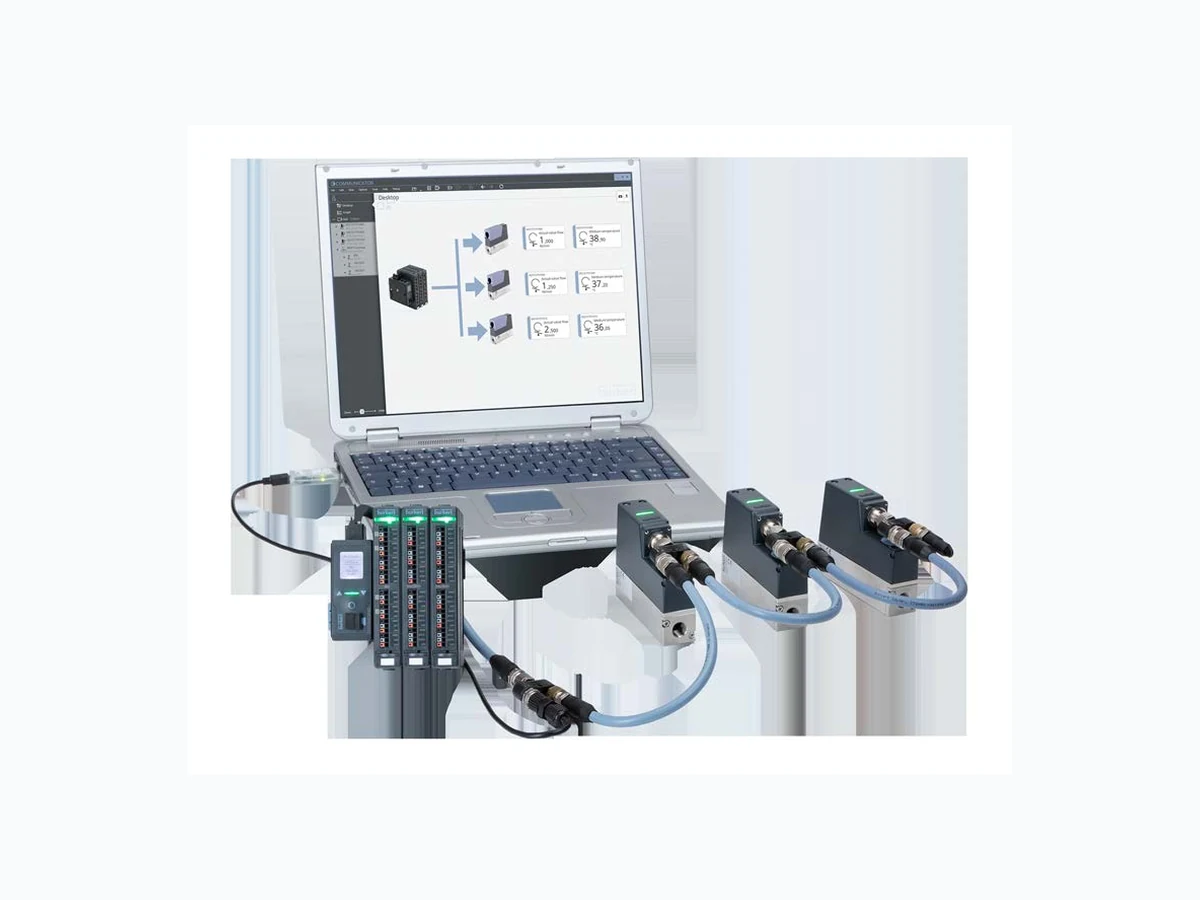
The default baud rate of all Bürkert devices is 500 kbit/s. In the case of a poor measurement result, it is possible to reduce the baud rate to 250 kbit/s or 125 kbit/s. Therefore, longer cables can be used in the network. Please note that the total time of a firmware update increases when the baud rate is reduced to a lower communication speed. 12.6 büS stick The büS stick is a USB-to-CAN converter and is connected to a laptop/PC with the Bürkert Communicator. It is used for the diagnostics, start-up and parameterisation of devices.
12.7 Stub lines
The total length of stub lines in the entire network should be reduced as much as possible. It is impossible to calculate exactly the impact that a one metre stub line has on reducing the signal quality in percentage terms.
12.8 Bus load
The maximum bus load is 40%. The specific bus load of a device is specified in the communication data sheet. To calculate the total bus load, sum up the values from the communication data sheet for all devices.
Type büS Best practice instructions
12.9 Power consumption
It is important to consider the power consumption of a device as early as possible in the planning. Using the information about the total power consumption of the network, the accessories and the number of power supplies can be planned. Furthermore, the permitted voltage ripple of a device must be considered. For devices with direct access, e.g. MFCs, it is important to have a low residual ripple. For sensors, the impact is not that significant.
12.10 Grounding power supplies
Power supplies should not be earthed, but it is important to ensure galvanic isolation. Otherwise, huge loops may develop that can have a negative impact on the entire network.
12.11 Shielding of büS network
Provide good, continuous functional earth (FE) with low impedance and noise. If this cannot be ensured in the area of the büS network, use a low-impedance metallic cable duct or bypass conductor grounded on both sides to prevent compensation currents over büS shield. Connect devices of the internal shielding "None" directly to the büS strand (without stitch). The shielding must be on upstream or downstream devices in the network, but at least on end devices. Connect at least one point of büS shield directly to FE (e.g. by using a device with direct FE connection to shield). Keep a distance from H-Field emitting machines with high power consumption. If not possible, use metal duct grounded on both sides or multiple times for additional shielding of the büS cable .
Type büS büS networks with maximum network expansion 13 büS NETWORKS WITH MAXIMUM NETWORK EXPANSION Networks with varying devices, cable lengths, baud rates and topologies are tested. The networks shown here should only serve as examples of what is possible and are intended as a refer- ence point for your own setup. For large networks close to the limit or even above, it always makes sense to check the network quality.
13.1 Line topology
For the baud rates 500 kbit/s, 250 kbit/s and 125 kbit/s the maximum cable length and the maximum num- ber of devices have been determined. 13.1.1 500 kbit/s Communication of the entire büS network worked with up to 84 devices and 1 büS stick. The total cable length was 75 metres.
23 Devices
Termination resistor DiagnosticsTR PS Power supply PS PS Measurement point MP 21 Devices 8 Devices 9 Devices 5 m
11 Devices 10 m 3 Devices 4 Devices 5 Devices10 m 10 m
*25 m additional cable length for wiring the devices Fig. 36: 500 kbit/s, 84 devices, cable length 75 m Measurements with a maximum cable length of 100 metres was possible with 44 devices and 1 büS stick. A length of 100 metres is defined as the limit in the CANopen specification.
6 Devices
Termination resistor DiagnosticsTR PS Power supply PS PS Measurement point MP 9 Devices 9 Devices 25 m
11 Devices
20 m 4 Devices 5 Devices10 m TR MP MP *25 m additional cable length for wiring the devices Fig. 37: 500 kbit/s, 44 devices, cable length 100 m
Type büS büS networks with maximum network expansion 13.1.2 250 kbit/s The network was tested with 84 devices and a total cable length of 175 metres and worked without any er- rors. Termination resistor DiagnosticsTR PS Power supply PS PS Measurement point MP 21 Devices 8 Devices 9 Devices
11 Devices 50 m 3 Devices 4 Devices 5 DevicesTR MP
*25 m additional cable length for wiring the devices PS Fig. 38: 250 kbit/s, 84 devices, cable length 175 m The system setup consists of 41 büS devices and 1 büS stick with a total cable length of 250 metres, which is defined as the maximum.
14 Devices
Termination resistor DiagnosticsTR PS Power supply PS Measurement point MP 9 Devices 9 Devices
4 Devices 50 m 5 DevicesTR MP
*25 m additional cable length for wiring the devices PS 50 m Fig. 39: 250 kbit/s, 41 devices, cable length 250 m
Type büS büS networks with maximum network expansion 13.1.3 125 kbit/s The network can have a total cable length of 475 metres with 84 devices and 1 büS stick. Termination resistor DiagnosticsTR PS Power supply PS PS Measurement point MP 21 Devices 8 Devices 9 Devices
11 Devices 50 m 3 Devices 4 Devices 5 Devices100 mTR MP
*25 m additional cable length for wiring the devices PS 100 m 50 m PS Fig. 40: 125 kbit/s, 84 devices, cable length 475 m With 125 kbit/, it is possible to connect up to 53 devices with a total cable length of 500 metres.
17 Devices
Termination resistor DiagnosticsTR PS Power supply PS PS Measurement point MP 15 Devices 9 Devices
3 Devices 100 m 4 Devices 5 Devices75 mTR MP
*25 m additional cable length for wiring the devices PS 150 m PS Fig. 41: 125 kbit/s, 53 devices, cable length 500 m
Type büS büS networks with maximum network expansion
13.2 Star topology with a junction box
If a passive junction box is used, all the cables are stub lines. With a baud rate of 500 kbit/s, a total stub line length of 25 metres is permitted. The maximum length of each stub line is limited to 5 metres. If all the stub lines have the same length, the position of the termination resistor is irrelevant. Junction box Device 1 Device 3 Device 4 Device 5Device 2 5 m 5 m 5 m 5 m 0.5 m 5 m TR PS TR Termination resistor DiagnosticsTR PS Power supply Measurement point MP MP Fig. 42: Star topology with a junction box
13.3 Tree topology with a junction box
With a tree topology, a total cable length of 94 metres was measured with 23 devices in the network. The stub line length varies between 1 and 10 metres. Device 1 Device 3 Device 4 Device 5 Device 6 Device 2 10 m 5 m 10 m 5 m 0.5 m 10 m 5 m TR PS Termination resistor DiagnosticsTR PS Power supply Measurement pointMP MP Device 7 Device 9 Device 8 1 m TR Device 10 Device 11 Device 12 Device 13 Device 14 1 m 1 m 1 m 1 m 1 m 1 m 1 m Device 18 Device 19 Device 20 Device 21 Device 22 3 m 3 m 3 m 3 m 3 m 3 m 3 m 3 m Device 15 Device 16 Device 17 MP10 m7 m Fig. 43: Tree topology with a junction box
Type büS Troubleshooting
14 TROUBLESHOOTING
14.1 Sporadic disconnections
Description: In a faulty network, it is possible to experience sporadic disconnections. Therefore, one or more devices may disappear for a few seconds. This is an indication that something has gone wrong. Common problems: ▪ More or less than two termination resistors ▪ Total cable length is too long ▪ Total stub line length is too long ▪ Bus load is too high ▪ Undersized power supply Solution: ▪ Measurement of the impedance between CAN-High and CAN-Low. The impedance should be approx. 60 Ω ▪ Reduce the cable length ▪ Reduce the baud rate to the next lower communication speed ▪ Create power segments in the network with more power supplies and Y-connectors
14.2 Red LED (failure)
Description: The LED of a single device or the entire EDIP network lights up red. Common problems: ▪ Incorrect connection to the PLC ▪ Device reached critical limit, e.g. power supply too low ▪ EDIP partner is missing Solution: ▪ Check the cabling to the PLC and configure the PLC with the description files of the device ▪ Check the messages of the device with the PLC or Bürkert Communicator ▪ Check the partner name and mapping
14.3 Orange LED on the device (functional check)
Description: The LED of a single device or the entire EDIP network lights up orange.
Type büS Troubleshooting Common problems: ▪ Partner allocation is active ▪ PLC has “stopped” ▪ Simulation is active ▪ Manual mode Solution: ▪ Wait until the device finds its partner in the network ▪ Set the PLC to “RUN” ▪ Deactivate simulation ▪ Set the device to “Automatic”
14.4 Yellow LED on the device (out of specification)
Description: The LED of a single device or multiple devices in the network lights up yellow. Common problems: ▪ Device has reached an internal limit, e.g. temperature ▪ Teach function is required ▪ Device cannot reach the setpoint Solution: ▪ Check the limits and messages with the PLC or Bürkert Communicator ▪ Start the device teach function ▪ Check the medium pressure
14.5 Blue LED on the device (maintenance required)
Description: The LED of a single device or multiple devices in the network lights up blue. Common problems: ▪ Switching cycle counter limit has been reached ▪ Config-Provider/Client missing ▪ Damaged calibration curve Solution: ▪ Reset the switching cycle counter ▪ Replace the missing device ▪ Recalibrate the device
Type büS Troubleshooting
14.6 Restarting some devices
If the LED first lights up yellow and then turns red or green, it is an indication that the power supply has reached a limit for stable operation. If one device switches an actor on, the voltage drop is so high that the power falls below the limit and a restart will be performed.
Type büS Appendix
15 APPENDIX
15.1 Accessories - büS stick interface sets
Accessories - büS stick interface sets Bürkert order no. USB-büS interface set 1 00772426 USB-büS interface set 2 00772551 Tab. 8: büS stick
15.2 Accessories - connectors
Accessories - connectors Bürkert order no. büS connector, female, M12 00772416 büS connector, male, M12 00772417 büS connector, female angled, M12 00772418 büS connector, male angled, M12 00772419 büS Y-connector, M12 00772420 büS Y-connector, M12 with interrupt 00772421 büS gender changer 00772867 büS termination, male, M12 00772424 büS termination, female, M12 00772425 Terminal block 4 pin with termination 00566066 Termination chip resistor ME43 00303833 Tab. 9: Connectors
15.3 Accessories - cables (open leads)
Accessories - cables (open leads) Bürkert order no. büS connecting cable 0.7 m 00772626 büS connecting cable 1 m 00772409 büS connecting cable 3 m 00772410 büS connecting cable 5 m 00772411 büS connecting cable 10 m 00772412 büS connecting cable 50 m (cable drum) 00772413 büS connecting cable 100 m (cable drum) 00772414 büS service cable, micro-USB-to-M12 00773254 Tab. 10: Cables (open leads)
Type büS Appendix
15.4 Accessories - extension cables
Accessories - extension cables Bürkert order no. büS extension cable 0.1 m 00772492 büS extension cable 0.2 m 00772402 büS extension cable 0.5 m 00772403 büS extension cable 1 m 00772404 büS extension cable 3 m 00772405 büS extension cable 5 m 00772406 büS extension cable 10 m 00772407 büS extension cable 20 m 00772408 Tab. 11: Extension cables
15.5 Accessories - power supplies
Accessories - power supplies Bürkert order no. Power supply, 1A, NEC Class 2 00772361 Power supply, 2A, NEC Class 2 00772362 Power supply, 3.8A, NEC Class 2 00772898 Power supply, 10A 00772698 Tab. 12: Power supplies
15.6 Accessories - power cables
Accessories - power cables (L-coded M12 plug to M12 socket, 4-pin) Bürkert order no. Power cable, L-coded, 1 m 00775061 Power cable, L-coded, 3 m 00775063 Power cable, L-coded, 5 m 00775064 Power cable, L-coded, 10 m 00775065 Tab. 13: Power cables Further accessories available on the Bürkert homepage.